Sludge suction vehicle applied in deep sewage well

A technology of sewage suction trucks and water wells, applied in the field of sewage suction trucks, can solve the problems of long time consumption, polluted air, and difficulty in cleaning and transporting equipment

Inactive Publication Date: 2018-09-04
梁策
View PDF10 Cites 0 Cited by
  • Summary
  • Abstract
  • Description
  • Claims
  • Application Information

AI Technical Summary

Problems solved by technology

Due to the ups and downs of the city, some sewer wells are deep, and ordinary sewage suction trucks cannot suck up the silt. The silt in the inspection well is a non-Newtonian fluid, which belongs to the category of Bingham (Bingham) body and is in a semi-solid and semi-fluid state. In the flow-plastic state, the existing technology and equipment are difficult to clean and transport, and it takes a long time to consolidate. The treatment method is quite primitive. The sludge and sand in the inspection shaft are manually dug out and then transported away. The sludge and sand and the stench along the way not only pollute the air, but also damage the image of a modern city

Method used


Image

  • Sludge suction vehicle applied in deep sewage well
  • Sludge suction vehicle applied in deep sewage well
  • Sludge suction vehicle applied in deep sewage well

Examples


Embodiment 1

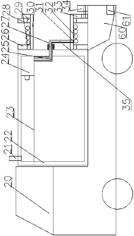
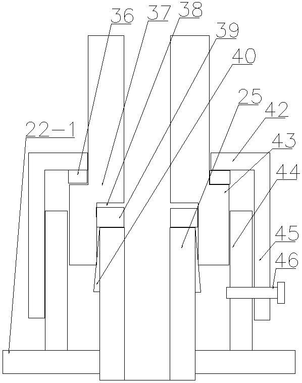
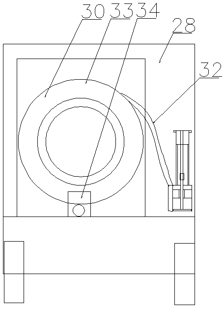
[0032] Embodiment 1: as Figure 1-7 As shown, a sewage suction truck applied to deep sewer wells includes a sewage suction truck 20 and a liquid storage tank 22 arranged on the sewage suction truck 20, the sewage suction pump is located in the liquid storage tank, and the sewage suction pump 24 is located in the The upper part of the filter screen 23, the upper part of the liquid storage tank is provided with a cleaning door, which is convenient for removing the solids on the filter screen, and the filter screen is arranged obliquely to facilitate the removal of the solids; the sewage inlet pipe 25 of the sewage suction pump 24 passes through the liquid storage On the side wall of the tank, the sewage inlet pipe is coaxial with the reel. One side of the liquid storage tank is provided with a main support plate 26 and a secondary positive support plate 28. Both the main support plate and the secondary positive support plate are provided with circular shaft holes. , the circular...

Embodiment 2

[0044] Embodiment 2: as figure 2 , 3 , 4, a sewage suction truck applied to deep sewer wells, comprising a sewage suction truck 20 and a liquid storage tank 22 arranged on the sewage suction truck 20, the sewage suction pump is located in the liquid storage tank, and the sewage suction pump 24 is located on the upper part of the filter screen 23, and the upper part of the liquid storage tank is provided with a cleaning door, which is convenient for removing solids on the filter screen, and the filter screen is arranged obliquely, which is convenient for cleaning out the solids; the sewage suction pipe 25 of the sewage suction pump 24 passes through The side wall of the liquid storage tank, the sewage inlet pipe 25 is coaxial with the reel, the side of the liquid storage tank 22 is provided with a main support plate 26 and a secondary positive support plate 28, and the main support plate and the secondary positive support plate are provided with Circular shaft hole, a bearing 2...

Embodiment 3

[0055] Embodiment 3: A sewage suction vehicle applied to deep sewer wells, including a sewage suction vehicle 20 and a liquid storage tank 22 arranged on the sewage suction vehicle 20, the sewage suction pump is located in the liquid storage tank, and the sewage suction pump 24 Located on the upper part of the filter screen 23, the upper part of the liquid storage tank is provided with a cleaning door, which is convenient for removing solids on the filter screen, and the filter screen is arranged obliquely to facilitate cleaning out the solids; the sewage suction pipe 25 of the sewage suction pump 24 passes through the storage tank. The side wall of the liquid tank, the sewage inlet pipe is coaxial with the reel, and the main support plate 26 and the auxiliary positive support plate 28 are arranged on one side of the liquid storage tank, and the main support plate and the auxiliary positive support plate are both provided with circular shafts A bearing 29 is arranged in the cir...


PUM


Abstract

The invention discloses a sludge suction vehicle applied in a deep sewage well. The sludge suction vehicle comprises a sludge suction vehicle body and a liquid storage tank arranged on the same, a sludge suction pump is positioned in the liquid storage tank, a sludge incoming pipe of the sludge suction pump penetrates out of the side wall of the liquid storage tank, a main supporting plate and anauxiliary supporting plate are arranged on one side of the liquid storage tank, each of the main supporting plate and the auxiliary supporting plate is provided with a round shaft hole, a bearing is arranged in each round shaft hole, and a rolling barrel is arranged in each bearing. Operation personnel performs dredging operation on the ground, so that a mode that a worker goes down into the wellis replaced, operation efficiency is improved, and safety and reliability are realized; the whole sludge treatment process is safe, efficient, simple and reliable and meets related laws and regulations on environment protection.

Description

technical field [0001] The invention belongs to the technical field of sediment and sundry treatment in deep wells, and in particular relates to a sewage suction truck used in deep wells. Background technique [0002] The inspection well is used in the turning, branching, falling, etc. of the drainage pipe to facilitate inspection and dredging, that is, the sewer inspection well in the middle of the road. The urban inspection wells buried underground gradually accumulate thicker and thicker silt layers. Once the rainwater continues, it will block the drainage pipes, affect urban drainage, and bring great hidden dangers to urban flood control. It needs to be cleared in time. According to research, urban manhole silt, which is neither solid nor liquid, belongs to the Bingham body category. This kind of sludge is in a plastic state and flowing state, and has the characteristics of smelly, sticky, soft, and black. In the past, there was no advanced suction method, and it has a...

Claims


Application Information

Patent Timeline
Patent Type & Authority Applications(China)
IPC IPC(8): E03F7/10B01D35/027
CPCB01D35/0273E03F7/10E03F7/106
Inventor 梁策
Owner 梁策
Why Eureka
Try Eureka