
Non-damage stiffness-adjustable prefabricated frame beam and column connection structure and construction method thereof

A beam-column connection without damage technology, which is applied in building construction and construction, can solve problems such as difficult quality assurance, inability to effectively realize strong columns and weak beams, and difficult construction of steel bar lapping, achieving convenient processing and high cost performance , The effect of convenient construction

Inactive Publication Date: 2018-09-04
CHINA STATE CONSTRUCTION ENGINEERING CORPORATION
View PDF3 Cites 10 Cited by
  • Summary
  • Abstract
  • Description
  • Claims
  • Application Information

AI Technical Summary

Problems solved by technology

[0003] The purpose of the present invention is to provide a non-damage adjustable stiffness prefabricated frame beam-column connection structure and its construction method, to solve the technical problem that the existing beam-column connection cannot effectively realize strong columns and weak beams, and to solve the prefabricated assembly system cast-in-place There are still technical problems in the construction of steel bar lap joints that are difficult to guarantee and the quality of which is difficult to guarantee

Method used

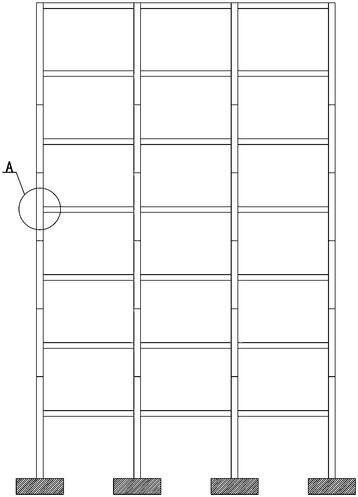

Image

  • Non-damage stiffness-adjustable prefabricated frame beam and column connection structure and construction method thereof
  • Non-damage stiffness-adjustable prefabricated frame beam and column connection structure and construction method thereof
  • Non-damage stiffness-adjustable prefabricated frame beam and column connection structure and construction method thereof

Examples


Embodiment Construction

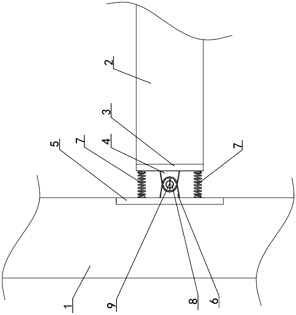
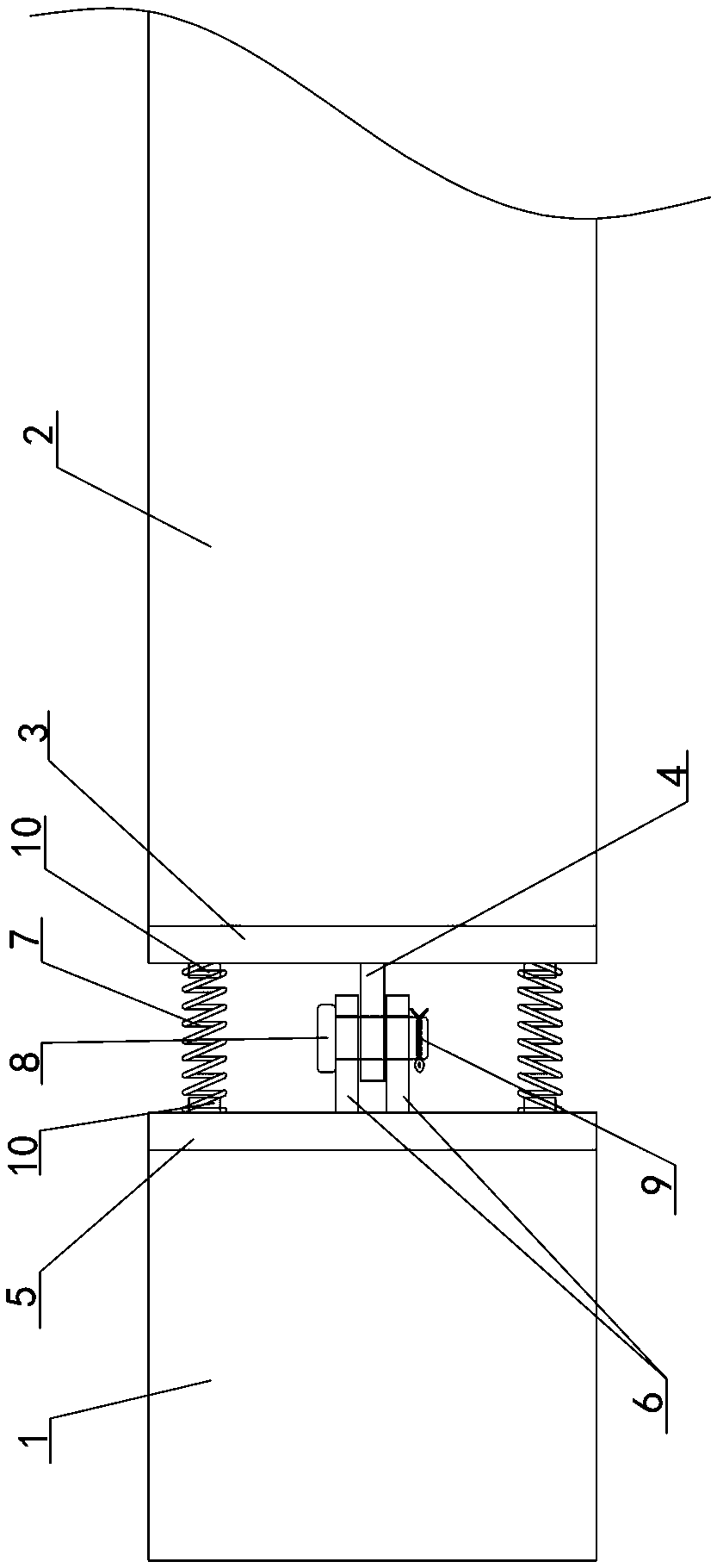
[0038] Embodiment Referring to the figure, a prefabricated beam-column connection structure with adjustable stiffness without damage includes prefabricated columns 1 and prefabricated beams 2 connected. In this embodiment, both the prefabricated column 1 and the prefabricated beam 2 are reinforced concrete prefabricated components.

[0039] Between the beam end center of the prefabricated beam 2 and the prefabricated column 1, a pin connection device is fixed so that the beam end of the prefabricated beam 2 can freely rotate up and down relative to the prefabricated column 1, and the pin connection device is a vertical shear connection ear The plate group, the shear connection ear plate group is penetrated with a pin joint shaft 8, and the pin joint shaft is located in the middle of the reserved space between the reinforced concrete column 1 and the prefabricated beam 2.

[0040] A vertical beam end plate 3 is pre-embedded on the beam end surface of the prefabricated beam 2 , ...


PUM


Abstract

The invention discloses a non-damage stiffness-adjustable prefabricated frame beam and column connection structure and a construction method thereof. The non-damage stiffness-adjustable prefabricatedframe beam and column connection structure comprises a prefabricated reinforced concrete column and a prefabricated beam which are connected; a pin joint device which enables the beam end of the prefabricated beam to vertically and freely rotate relative to the prefabricated column is fixed between the center of the beam end face of the prefabricated beam and the prefabricated column; the pin joint device is a vertical shear-resisting connecting lug plate set, and a pin joint shaft is arranged on the shear-resisting connecting lug plate set in a penetrating mode; and the pin joint shaft is located in the middle of a reserved gap between the reinforced concrete column and the prefabricated beam. Compared with the ideas of bending and shearing separation, strong shearing and weak bending, and bending shearing elasticity, a pre-embedded piece capable of being accurately positioned is prefabricated in a factory through a fabricated structure, processing is convenient, on-site mounting of the structure is easy and convenient, the mounting efficiency is improved, the economic feasibility is achieved, and the performance cost ratio is high; and structural steel bars are completely disconnected, the steel bar overlapping problem is avoided, and the advantage of convenient construction is achieved in the real sense.

Description

technical field [0001] The invention relates to a frame structure beam-column connection structure, in particular to a prefabricated frame beam-column connection with adjustable stiffness without damage and a construction method thereof. Background technique [0002] Due to the promotion of economic development and technological progress, as well as the huge housing demand and labor shortage in the process of urbanization, the foundation has been laid for the industrialization of housing and the application of prefabricated components. The prefabricated structure is a concrete structure made of prefabricated components as the main component, assembled, connected, and partially cast in place. It has high construction efficiency, low cost, and conforms to the green construction principle of "four sections and one environmental protection". It is the development direction of the civil engineering field. According to Article 6.1.1 of JGJ1-2014 Technical Regulations for Prefabri...

Claims


Application Information

Patent Timeline
IPC IPC(8): E04B1/21
CPCE04B1/21E04B1/215
Inventor 张翠强王鹏史鹏飞李六连田振孙建运
Owner CHINA STATE CONSTRUCTION ENGINEERING CORPORATION
Learn More