
Four-degree-of-freedom magnetic suspension rotating cylinder

A technology of magnetic levitation and degree of freedom, applied to magnetic bearings, bearings, shafts and bearings, etc., can solve the problems of high machining accuracy and installation accuracy, difficulty in drum design, installation and debugging, and inflexible position adjustment

Active Publication Date: 2018-09-04
TSINGHUA UNIV
View PDF12 Cites 5 Cited by
  • Summary
  • Abstract
  • Description
  • Claims
  • Application Information

AI Technical Summary

Problems solved by technology

However, since the stable levitation of the magnetic levitation rotor needs to consider the non-linearity of the permanent magnet magnetic field and satisfy Earnshaw's theorem, the processing accuracy and installation accuracy are high. It cannot be adjusted flexibly. If the relative position of the inner and outer magnetic rings is found to be slightly mismatched during assembly, the rotor and the magnetic ring can only be remade, which makes it difficult to reduce the processing cost and scrap rate. The position cannot be adjusted flexibly, and it is also difficult to realize the four-degree-of-freedom design, installation and commissioning of the drum

Method used


Image

  • Four-degree-of-freedom magnetic suspension rotating cylinder
  • Four-degree-of-freedom magnetic suspension rotating cylinder
  • Four-degree-of-freedom magnetic suspension rotating cylinder

Examples


Embodiment Construction

[0029] The specific implementation manners of the present invention will be further described in detail below in conjunction with the accompanying drawings and examples. The following examples are used to illustrate the present invention, but are not intended to limit the scope of the present invention.

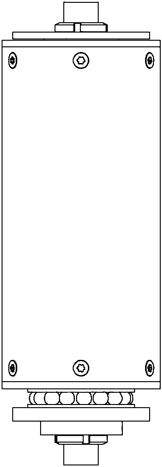
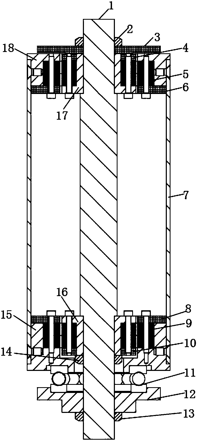
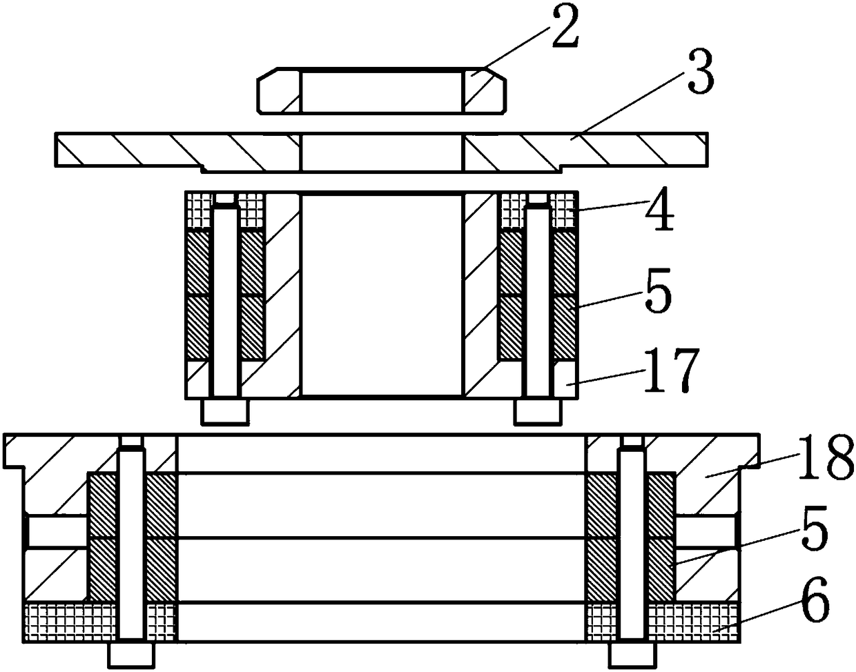
[0030] refer to Figure 1-6 As shown, the four-degree-of-freedom magnetic levitation drum of this embodiment includes a threaded shaft 1, an upper permanent magnetic radial bearing 5, a lower permanent magnetic radial bearing 6, a bearing adapter, an outer drum 7, and a translational thrust bearing 11 , Tray 12, lock nuts, bolts.

[0031] The upper and lower ends of the threaded shaft 1 are provided with fine threads, the thread lead angle of the threaded shaft 1 is smaller than the equivalent friction angle, the middle is an optical axis, and the diameter of the optical axis is greater than the outer diameter of the thread to form a shaft shoulder. The threaded shaft 1 is ...


PUM


Abstract

The invention provides a four-degree-of-freedom magnetic suspension rotating cylinder. The four-degree-of-freedom magnetic suspension rotating cylinder comprises a threaded shaft, permanent magnet radial bearings, a bearing switching component, an outer rotating cylinder, a translational thrust bearing and a tray; the threaded shaft is supported on the inner wall of the outer rotating cylinder through permanent magnet radial bearings, the outer rotating cylinder can rotate relative to the threaded shaft, and the lower portion of the outer rotating cylinder is supported on the tray through thetranslational thrust bearing; inner magnetic rings of the permanent magnet radial bearings can move up and down along the threaded shaft through the bearing switching component, so that the relative positions of the inner magnetic rings and outer magnetic rings can be flexibly adjusted; and the translationsl thrust bearing can achieve radial horizontal displacement while bearing axial force, and the translational range is larger than or equal to the clearance range of the inner magnetic rings and the outer magnetic rings of the permanent magnet radial bearings so that the outer rotating cylinder can achieve stable suspension and rotation, and the outer rotating cylinder is not limited by the radial constraint of the translational thrust bearing. According to the four-degree-of-freedom magnetic suspension rotating cylinder, the novel magnetic suspension rotating cylinder is more convenient to install, the machining precision is reduced, and the bearing capacity is large; and the magnetic suspension rotating cylinder can adapt to various rotating speed working conditions and is suitable for supporting a rotary machine requiring radial contact-free, lubrication-free, high-speed and passive environments.

Description

technical field [0001] The invention relates to a magnetic levitation rotating device, in particular to a four-degree-of-freedom magnetic levitation drum, which is suitable for environments where rotating machines require radial non-contact, no lubrication, and no source. Background technique [0002] In the field of rotating machinery technology, with the development of technology, the requirements for the rotation speed of bearings are getting higher and higher. Traditional mechanical bearings generate heat, wear quickly, and consume a lot of energy under high-speed operation, and cannot better meet the high-speed requirements of some ultra-high-speed operating equipment, such as the centrifugal separator used in the isotope separation of uranium. In order to improve the single-stage separation power, which requires the rotor to operate at supercritical speeds. The use of magnetic suspension bearings instead of traditional mechanical bearings to support high-speed rotatin...

Claims


Application Information

Patent Timeline
Patent Type & Authority Applications(China)
IPC IPC(8): F16C32/04F16C13/02
CPCF16C13/024F16C32/0408
Inventor 于溯源苏一新马彦会
Owner TSINGHUA UNIV
Learn More