Micro mass sensor

A sensor and micro-mass technology, applied in the field of sensors, can solve the problems of small electrostatic driving force, weak amplitude, affecting the accuracy of micro-mass measurement, etc., and achieve the effect of high sensitivity and suppression of interference

Active Publication Date: 2018-09-04
WENZHOU UNIVERSITY
View PDF14 Cites 0 Cited by
  • Summary
  • Abstract
  • Description
  • Claims
  • Application Information

AI Technical Summary

Problems solved by technology

Domestic and foreign literature also shows that due to the deformation of the entire beam structure or plate structure during operation, if micromass matter is sporadically adsorbed on these structures in the form of particles or unevenly distributed on these structures, its random position can have a significant impact on the vibration frequency. , and thus affect the measurement accuracy of micromass
In addition, due to the limited electrode area that can be arranged in the beam structure, the electrostatic driving force is small, and the generated amplitude is weak, which is not conducive to detection, and is easily disturbed by external mechanical loads. When the vibration information is extracted by capacitive detection When the electrode area is small, the capacitance value between the electrodes is small, so it is easily disturbed by stray capacitance; the plate structure also has the disadvantage of weak amplitude due to its high rigidity.

Method used


Image

  • Micro mass sensor
  • Micro mass sensor
  • Micro mass sensor

Examples


Embodiment Construction

[0018] Embodiments of the present invention will be further described below in conjunction with accompanying drawings:

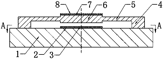
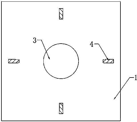
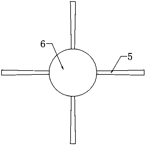
[0019] In an embodiment of the present invention, a micromass sensor includes: a substrate 1, a fixed electrode 2 disposed on the substrate 1, an adsorption layer 8, the fixed electrode is covered with a first insulating layer 3, and the substrate 1 is also provided with A vibration structure, the vibration structure includes a metal movable plate 6, a support beam 5 and an anchor point 4 of the beam, the metal movable plate 6 is connected to the support beam 5, and is fixed on the base 1 through the anchor point 4.

[0020] The movable plate 6 is a rigid circular plate, and each support beam is evenly distributed on the edge of the movable plate 6 . Since the maximum bending stress of the plate-beam structure occurs at the fixed end of the beam, the beam adopts a variable cross-section beam with a large cross-sectional area at the fixed end. The adsorption...


PUM


Abstract

The invention provides a micro mass sensor which comprises a substrate, a fixed electrode arranged on the substrate and an adsorption layer. A vibration structure is further arranged on the substrate,and the vibration structure comprises a metal movable plate, a support beam and an anchoring point of the beam. The metal movable plate is connected to the support beam and is fixed to the substratethrough the anchoring point. The metal movable plate simultaneously serves as a movable electrode, and a variable capacitor is formed by the movable electrode and the fixed capacitor. The micro mass sensor works by using the principle that a micro-mass substance is adsorbed on the vibration structure and then the change of a vibration frequency is caused. The vibration structure is formed by the movable plate and the support beam, the influence of the position of a micro mass on the vibration structure on a measurement result can be effectively suppressed, with the metal movable plate as the movable electrode, an area is large, the increase of the static driving force on the movable electrode is facilitated, the increase of a capacitance value between the movable and fixed electrodes is facilitated, and the improvement of the anti-interference of the sensor is facilitated.

Description

technical field [0001] The invention relates to the field of sensors, in particular to a micromass sensor with a vibration structure composed of a circular plate and a support beam and based on vibration frequency measurement and electrostatic drive. Background technique [0002] Micromass detection technology has important application significance in environmental monitoring, biomedicine and other fields. The vibration frequency of the vibrating body is very sensitive to mass changes, so micromass detection can be realized based on this. After retrieving domestic and foreign literature, it is found that the vibration structure of the existing electrostatically driven micromass sensors based on vibration frequency measurement is mainly a beam structure, and some are plate structures. Domestic and foreign literature also shows that due to the deformation of the entire beam structure or plate structure during operation, if micromass matter is sporadically adsorbed on these st...

Claims


Application Information

Patent Timeline
Patent Type & Authority Applications(China)
IPC IPC(8): G01G9/00
CPCG01G9/00
Inventor 李凯彭志辉
Owner WENZHOU UNIVERSITY
Why Eureka
Try Eureka