Safe and reliable intelligent mobile payment equipment with moisture-proof function

A mobile payment, intelligent technology, applied in the payment system, payment system structure, cleaning method and utensils, etc., can solve the problems of reduced practicability of mobile payment equipment, easy access to water, property loss of mobile phone users, etc., to prevent property loss. , The effect of preventing moisture and scratches

Inactive Publication Date: 2018-09-04
SHENZHEN NAISHIDI TECH DEV CO LTD
0 Cites 5 Cited by

AI-Extracted Technical Summary

Problems solved by technology

[0003] Although the existing mobile payment devices are easy to carry and convenient for transactions, most of these devices have certain environmental requirements, especially mobile phones, which are difficult to use in rainy days and are prone to water, so special atten...

Abstract

The invention relates to safe and reliable intelligent mobile payment equipment with a moisture-proof function, and the equipment comprises a main body, a sealing plate, a recognition mechanism, and two watchbands. The interior of the main body is provided with a payment mechanism, and the payment mechanism comprises a telescoping module, a translating rod, and a display panel. The telescoping module comprises a motor and two telescoping units. The recognition mechanism comprises a recognition box, a top plate, a shading plate, a bottom plate, a roller, a rolling shaft, and two sliding rods. The interior of the recognition box is provided with a processor, a fingerprint window, and a resetting module. The equipment enables the display panel to move out of the main body through the paymentmechanism, and enables the display panel to move into the main body after the payment information is displayed. The sealing plate achieves the sealing, and prevents a wetting condition. Moreover, theequipment can achieve the payment only after the identity verification, thereby avoiding the bigger property loss caused by the loss of the equipment, and guaranteeing the safety and reliability.

Application Domain

Technology Topic

Image

  • Safe and reliable intelligent mobile payment equipment with moisture-proof function
  • Safe and reliable intelligent mobile payment equipment with moisture-proof function
  • Safe and reliable intelligent mobile payment equipment with moisture-proof function

Examples

  • Experimental program(1)

Example Embodiment

[0026] The present invention will now be described in further detail with reference to the drawings. These drawings are all simplified schematic diagrams, which merely illustrate the basic structure of the present invention in a schematic manner, so they only show the structures related to the present invention.
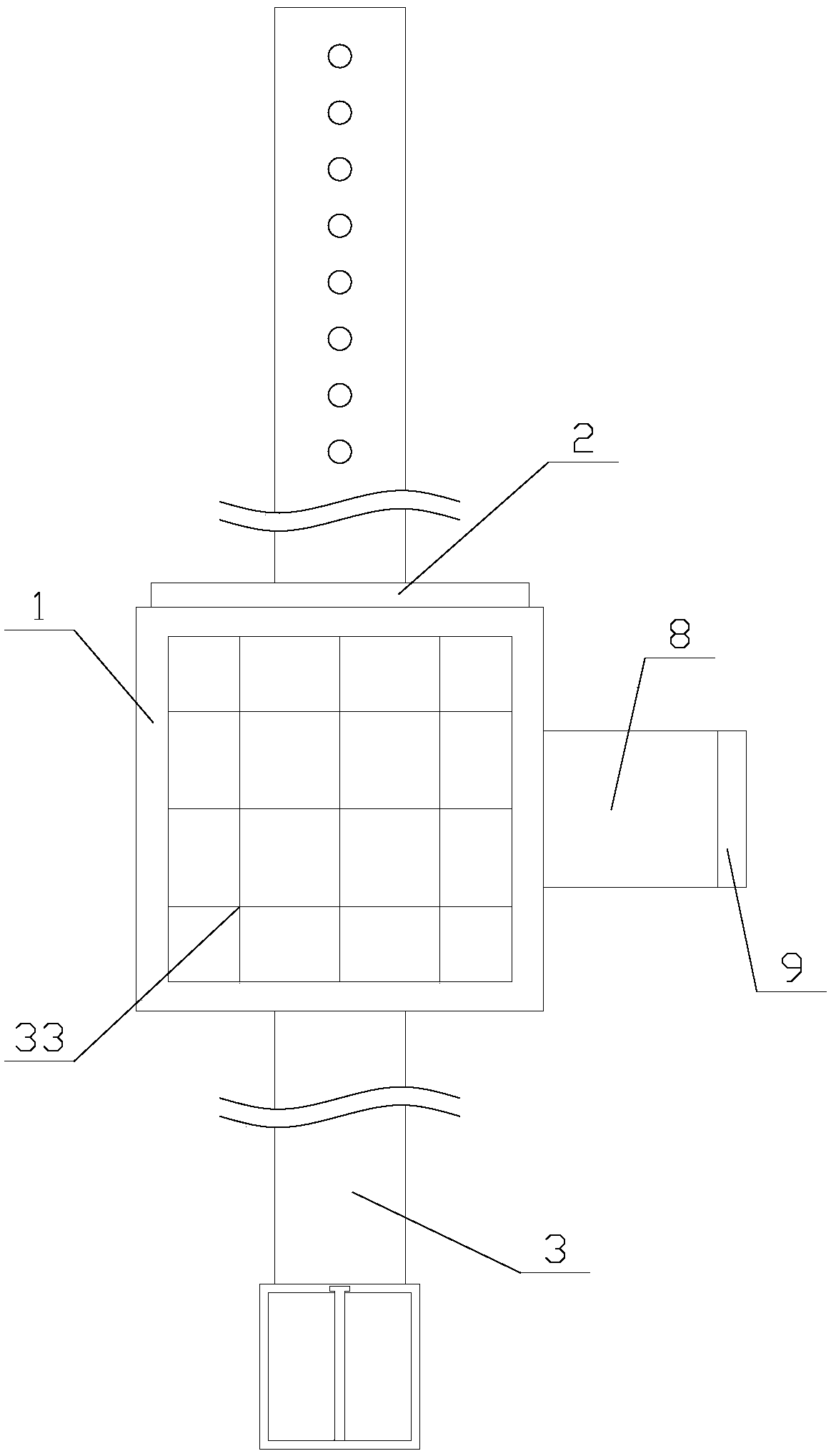
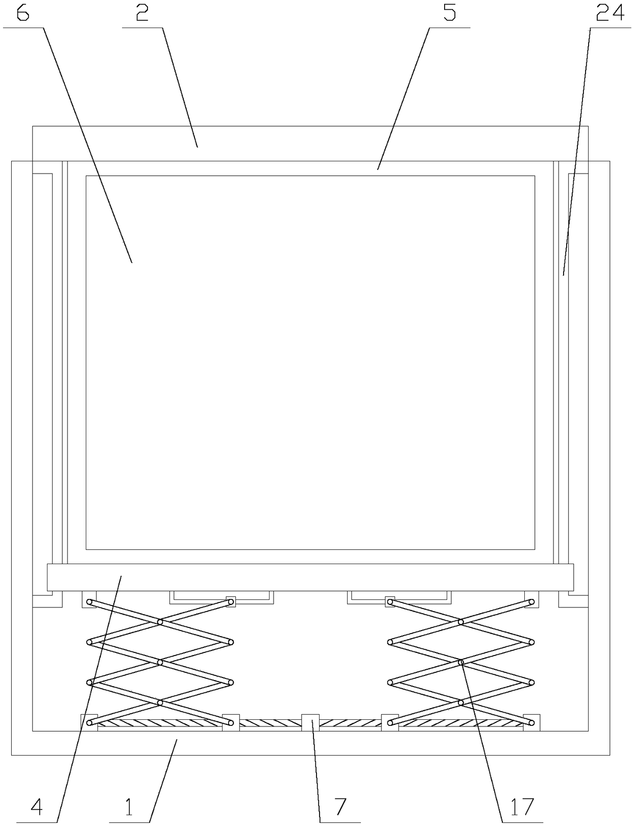
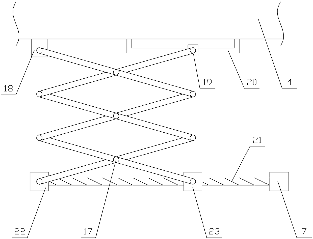
[0027] Such as figure 1 As shown, a safe and reliable intelligent mobile payment device with moisture-proof function includes a main body 1, a sealing plate 2, an identification mechanism, and two watch bands 3. The two watch bands 3 are located on both sides of the main body 1, and two In the watch bands 3, one of the watch bands 3 is provided with a number of sockets, and the other watch band 3 is provided with a fixing frame and a fixing pin at an end away from the main body 1, and the sealing plate 2 is located above one of the watch bands 3. The identification mechanism is located on one side of the main body 1, and the main body 1 is provided with a payment institution and a PLC;
[0028] When the mobile payment device is used, the main body 1 is worn on the wrist, and then the watchband 3 is passed through the fixing frame, and the pin is used to pass through the socket on the watchband 3 to realize the fixation of the device. During payment transactions, Put your finger into the identification agency to perform fingerprint identification, and the device performs user authentication. After confirming the legal identity, the payment information is displayed through the payment agency to facilitate the transaction. Since identity authentication is required during payment, even if the user loses the mobile payment device Later, others cannot use the device to pay, thereby ensuring the safety and reliability of the mobile payment device.
[0029] Such as figure 2 As shown, the payment mechanism includes a telescopic component, a translation rod 4 and a display board 5. The telescopic component is located at the bottom of the main body 1, the telescopic component, the translation rod 4 and the display board 5 are arranged in sequence, and the display board 5 It is fixedly connected to the sealing plate 2, the display board 5 is provided with a display screen 6, the telescopic assembly includes a motor 7 and two telescopic units, the two telescopic units are respectively located on both sides of the motor 7, the telescopic unit and the translation The rod 4 is connected, the motor 7 is fixed at the bottom of the main body 1, and both the motor 7 and the display screen 6 are electrically connected to the PLC;
[0030] When the payment institution needs to conduct a payment transaction, the PLC controls the operation of the motor 7 in the main body 1, and the motor 7 drives the operation of the telescopic unit to move the translation rod 4 to the outside of the main body 1, thereby exposing the display panel 5 to the outside of the main body 1 and displaying Payment information such as QR codes and barcodes are displayed on the screen 6, which is convenient for merchants to scan. When the transaction is completed, the motor 7 drives the translation rod 4 to move inside the main body 1 through the telescopic unit, so that the display board 5 moves into the main body 1, and is sealed The plate 2 realizes the sealing of the opening of the main body 1 to prevent external water flow from entering the inside of the main body 1, causing short circuit and damage to the equipment, affecting the use of the equipment, and realizing the moisture-proof function of the equipment.
[0031] Such as Figure 4-5 As shown, the identification mechanism includes an identification box 8, a top plate 9, a shutter 10, a bottom block 11, a roller 12, a roller 13 and two sliding rods 14. The identification box 8 is fixed on the main body 1, and the top plate 9 and the fixing block are respectively fixed at the top and bottom ends of the side far away from the main body 1 of the identification box 8. The top end of the shutter 10 is hinged with the top plate 9, and the roller 13 is located below the shutter 10. The two ends of the shaft 13 are respectively connected to two sliding rods 14, and the end of the sliding rod 14 away from the roller 13 is arranged in the shutter 10, the shutter 10 is provided with an elastic component, and the roller 12 abuts against Above the bottom block 11;
[0032] The identification box 8 is provided with a processor 15, a fingerprint window 16, and a resetting assembly. The resetting assembly is arranged on the top of the identification box 8. The resetting assembly is connected to the shutter 10, and the processor 15 is fixed in the identification box. At the bottom of the box 8, the fingerprint window 16 is fixed above the processor 15, and the processor 15 is electrically connected to the PLC.
[0033] When the identification mechanism is used, the user only needs to push the shutter 10 to move into the identification box 8. The fingerprint window 16 in the identification box 8 collects the user's fingerprint, and the processor 15 feeds back the fingerprint information to the PLC. After the PLC confirms that the identity is legal , Control the operation of the payment institution. After the transaction is completed, the user leaves the shutter 10, and the reset component drives the shutter 10 to rotate to return the shutter 10 to its original position. During the rotation of the shutter 10, the elastic components in the shutter 10 slide against each other. The lever 14 generates a downward force to move the roller 12 against the surface of the fingerprint window 16, and the roller 12 rolls along the surface of the fingerprint window 16, which can remove residual fingerprints on the surface of the fingerprint window 16 and prevent fingerprint information from being stolen. This further ensures the safety and reliability of the mobile payment device.
[0034] Such as image 3 As shown, the telescopic unit includes a driving unit, a telescopic frame 17, a hinge block 18, a slider 19, and a sliding rail 20. The driving unit is connected to one end of the telescopic frame 17, and the other end of the telescopic frame 17 is on both sides They are respectively hinged with a hinge block 18 and a sliding block 19, the sliding rail 20 is U-shaped, both ends of the sliding rail 20 and the hinge block 18 are fixed on the translation rod 4, and the sliding block 19 is sleeved on On the slide 20.
[0035] The motor 7 runs, and the telescopic frame 17 is driven by the drive unit to expand and contract, so that the slider 19 slides on the slide rail 20, thereby driving the translation rod 4 to move, and the translation rod 4 drives the display panel 5 to move, so that the display panel 5 enters the main body 1 Or move to the outside of the main body 1.
[0036] Preferably, in order to realize the expansion and contraction of the telescopic frame 17, the drive unit includes a drive shaft 21, a bearing 22 and a moving block 23. The bearing 22 is fixed at the bottom of the main body 1, and the drive shaft 21 is located between the bearing 22 and the motor 7. In between, the motor 7 is in transmission connection with the drive shaft 21, the moving block 23 is sleeved on the drive shaft 21, and the moving block 23 and the bearing 22 are respectively connected to the two sides of the telescopic frame 17 that is away from the translation rod 4 For articulation, the connection between the moving block 23 and the drive shaft 21 is provided with a thread matching the drive shaft 21. The motor 7 drives the drive shaft 21 to rotate. The drive shaft 21 acts on the moving block 23 through threads to move the moving block 23 along the axis of the drive shaft 21, thereby changing the distance between the moving block 23 and the bearing 22 , Thereby driving the telescopic frame 17 to expand and contract.
[0037] Preferably, in order to ensure the smooth movement of the display panel 5, a limit frame 24 is provided on both sides of the translation rod 4, the shape of the limit frame 24 is U-shaped, and both ends of the limit frame 24 are fixed to the main body On the inner wall of 1, the translation rod 4 is sleeved on the limit frame 24. The limit frame 24 is used to fix the moving direction of the translation rod 4, so that the display panel 5 keeps moving smoothly.
[0038] Such as Figure 4 As shown, the reset assembly includes a reset tube 25, a drive rod 26, and a support rod 27. The reset tube 25 is fixed at the top of the identification box 8. One end of the drive rod 26 is set in the reset tube 25. The other end of the drive rod 26 is hinged to the center of the shutter 10 through the support rod 27, a first spring 34 is provided in the reset tube 25, and one end of the first spring 34 is connected to the bottom of the reset tube 25, so The other end of the first spring 34 is connected to the driving rod 26, and the first spring 34 is in a compressed state.
[0039] When the finger is released from the shutter 10, the compressed first spring 34 in the reset tube 25 is deformed and pushes the driving rod 26 to move to the outside of the reset tube 25, so that the driving rod 26 drives the shutter 10 to rotate through the support rod 27 to restore the original shape. Bit.
[0040] Preferably, in order to ensure the smooth movement of the driving rod 26, a limit ring 28 is also provided in the reset tube 25, and the limit ring 28 is fixed on the inner wall of the reset tube 25, and the limit ring 28 is sleeved on the driving rod. On the pole 26. The fixed position of the stop ring 28 is used to fix the moving direction of the driving rod 26 to keep the driving rod 26 moving smoothly.
[0041] Preferably, in order to limit the movable range of the shutter 10, a limit block 29 is provided on the side of the shutter 10 away from the reset component, and the limit block 29 is fixed under the top plate 9. The limit block 29 is used to limit the rotation range of the shutter 10 and prevent the shutter 10 from leaving the opening of the identification box 8.
[0042] Such as Figure 5 As shown, the elastic assembly includes a movable rod 30 and a number of second springs 31. The movable rod 30 is connected to the bottom of the shutter 10 through the second spring 31. The second spring 31 is in a compressed state. Both ends of the rod 30 are fixedly connected to the two sliding rods 14 respectively. The second spring 31 is compressed, and in order to restore the deformation, the movable rod 30 is driven to move to the outside of the shutter 10, so that during the rotation of the shutter 10, the sliding rod 14 moves away from the second spring 31, thereby causing the roller 12 abuts against the surface of the fingerprint window 16 to facilitate the removal of fingerprints on the surface of the fingerprint window 16.
[0043] Preferably, in order to ensure the smooth movement of the sliding rod 14, inner walls on both sides of the shutter 10 are provided with orientation rings 32, and the orientation rings 32 are sleeved on the sliding rod 14. The orientation ring 32 is used to fix the moving direction of the sliding rod 14 relative to the shutter 10, so that the sliding rod 14 keeps moving smoothly.
[0044] Preferably, in order to improve the endurance of the device, a solar panel 33 is provided above the main body 1. Photovoltaic power generation can be realized through the solar panel 33, which provides electrical energy for equipment operation, thereby improving the endurance of the equipment.
[0045] In this mobile payment device, the translation rod 4 is driven by a telescopic component. When the device is idle, the display panel 5 is moved into the main body 1, and the main body 1 is sealed by the sealing plate 2 to prevent the display panel 5 from getting wet. , Fingerprint recognition is performed through the fingerprint window 16. While the shutter 10 is automatically reset by the reset component, the roller 12 can clear the residual fingerprints on the fingerprint window 16. Even if the user accidentally loses the device, others cannot use the payment device for goods The transaction prevents users from suffering property losses, thereby ensuring the safety and reliability of the mobile payment device.
[0046] Compared with the prior art, this safe and reliable smart mobile payment device with moisture-proof function moves the display board 5 to the outside of the main body 1 through the payment mechanism. After displaying the payment information, the display board 5 is moved into the main body 1 and sealed The board 2 is sealed to prevent moisture. Compared with the existing payment institution, the payment institution receives the display board 5 into the main body 1 when the device is idle, and also prevents the display board 5 from being scratched and further protects the display screen 6. Not only that, the payment can only be realized after the device has been authenticated by the identification agency, preventing the user from causing more property losses when the device is lost. Compared with the existing identification agency, the identification agency can automatically remove the remaining fingerprint window 16 Fingerprints prevent others from stealing, which further ensures the safety and reliability of the device.
[0047] Taking the above-mentioned ideal embodiment according to the present invention as enlightenment, through the above-mentioned description content, relevant staff can make various changes and modifications without departing from the scope of the technical idea of ​​the present invention. The technical scope of the present invention is not limited to the content of the description, and its technical scope must be determined according to the scope of the claims.

PUM

no PUM

Description & Claims & Application Information

We can also present the details of the Description, Claims and Application information to help users get a comprehensive understanding of the technical details of the patent, such as background art, summary of invention, brief description of drawings, description of embodiments, and other original content. On the other hand, users can also determine the specific scope of protection of the technology through the list of claims; as well as understand the changes in the life cycle of the technology with the presentation of the patent timeline. Login to view more.

Similar technology patents

Classification and recommendation of technical efficacy words

  • Prevent moisture
  • Avoid scratches

Electronic paper apparatus

InactiveUS20080062506A1Prevent moistureEnhanced moisture resistanceNon-linear opticsOptical elementsClosed spaceElectronic paper
Owner:GIGNO TECH CO LTD

Continuous, quantitative and rotary feeder

InactiveCN106629126APrevent moisture from entering the material binPrevent moistureLoading/unloadingEngineeringMoisture
Owner:吴云萍

Cerium-based abrasive material and method for preparation thereof

InactiveUS7156888B2Good dispersion retentionAvoid scratchesPigmenting treatmentOther chemical processesDispersed mediaAfter treatment
Owner:MITSUI MINING & SMELTING CO LTD

Inner segment removing machine

ActiveCN104942926AEasy to interveneAvoid scratchesCane mechanical workingPlant material mechanical workingEngineeringPunching
Owner:FUJIAN LONTAI BAMBOO HOUSEHOLD CO LTD

Display panel and electronic equipment

ActiveCN106353930AAvoid scratchesImprove image display qualityNon-linear opticsEngineeringSurface plate
Owner:SHANGHAI TIANMA MICRO ELECTRONICS CO LTD +1
Why Eureka
Try Eureka