Multi-lead installation type shunt device

A shunt device, multi-conductor technology, applied in multi-conductor connectors, conductive connections, electrical components and other directions, can solve the problems of poor wire connection handling, weak wiring, cable shunt, etc., to achieve compact structure, flexible and convenient use, The effect of pressure equalization

Pending Publication Date: 2018-09-04
GUANGZHOU PANYU CABLE WORKS
View PDF0 Cites 4 Cited by
  • Summary
  • Abstract
  • Description
  • Claims
  • Application Information

AI Technical Summary

Problems solved by technology

[0002] It is very important to ensure the safe and stable operation of the power grid in today's society. The poor connection of wires has brought many troubles to people, such as the problem of cable shunting. In fact, this method often leads to weak wiring and disconnection, which brings certain losses to users and a lot of work for maintenance and emergency repair personnel.

Method used


Image

  • Multi-lead installation type shunt device
  • Multi-lead installation type shunt device
  • Multi-lead installation type shunt device

Examples


Embodiment 1

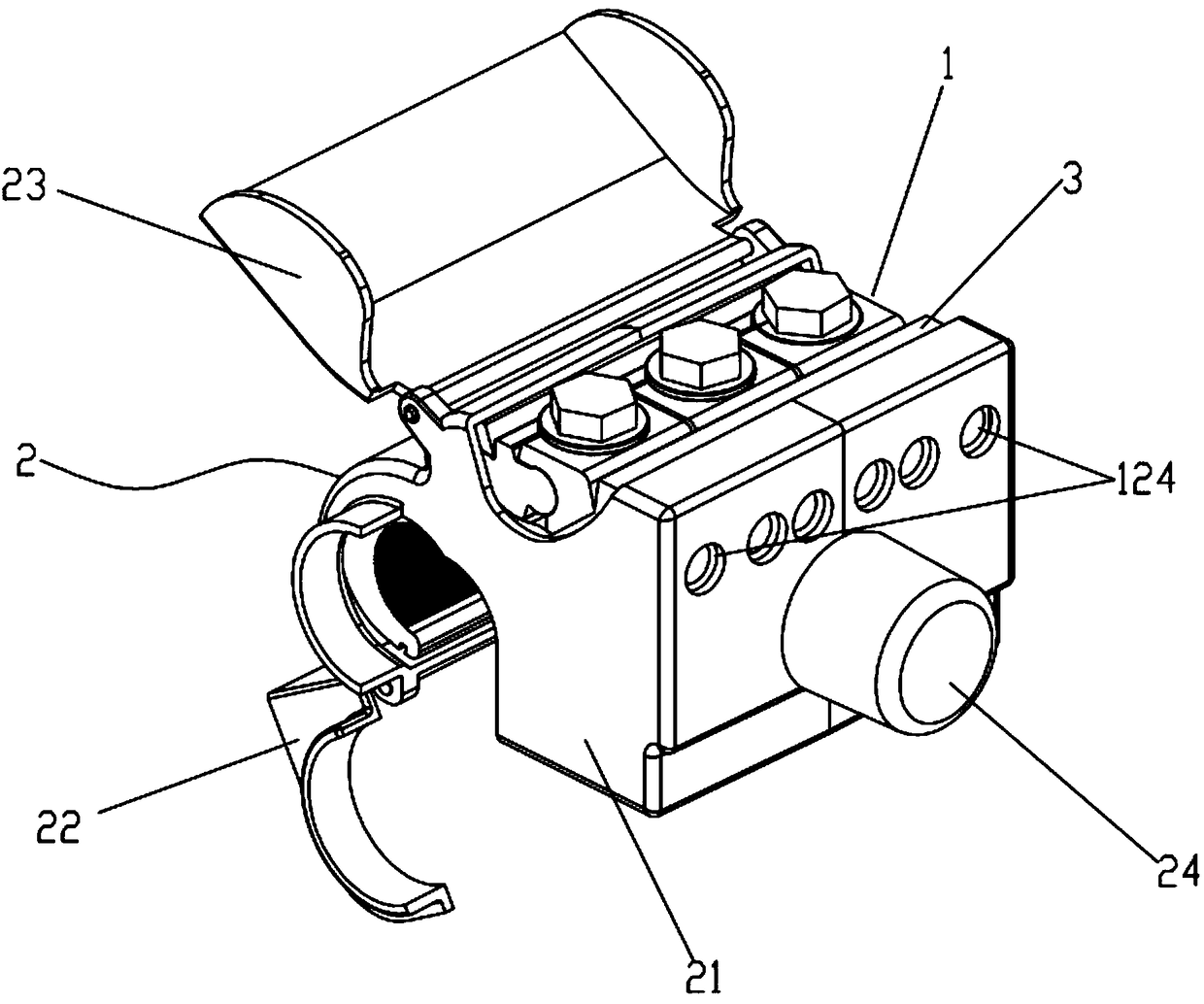
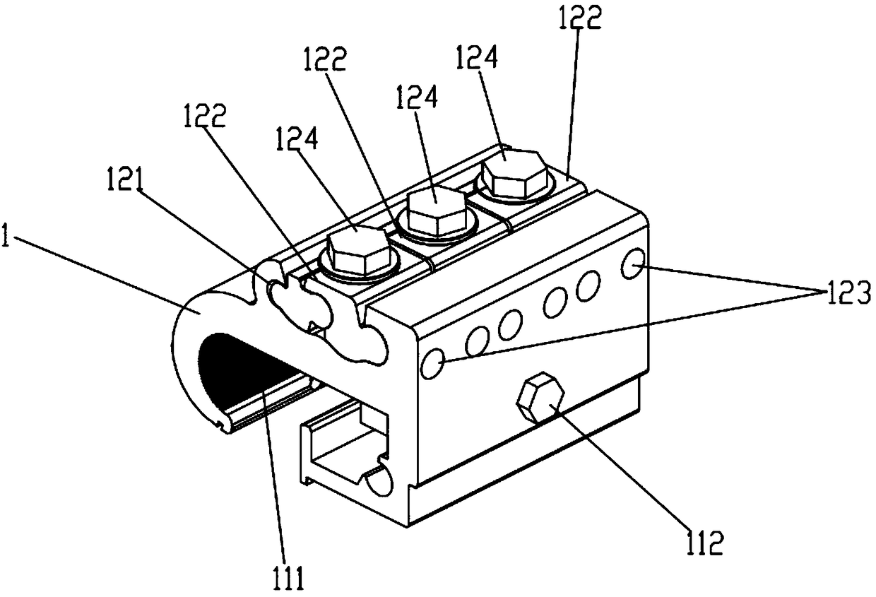
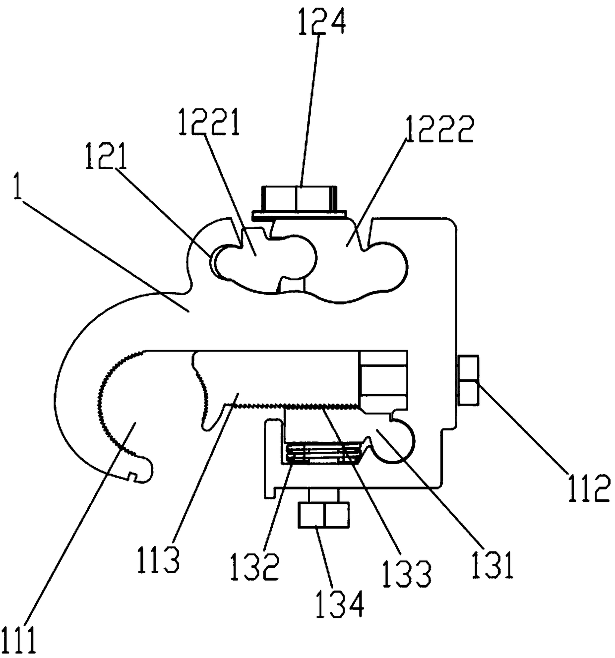
[0024] like Figure 1-4 As shown, the multi-wire installation type shunt device includes a conductive shunt seat 1 and an insulating shell 2 set outside the shunt seat 1, and a first groove 111 is provided on one side of the shunt seat 1, and the first groove 111 The main line screw 112 threaded on the groove wall at one end, the dynamic pressure block 113 placed in the first groove 111, the opposite sides of the first groove 111 are open for the main wire 4 to pass through, and one side of the dynamic pressure block 113 is connected to the main line. The screw 112 is rotatably connected, and the other side cooperates with the groove wall at the other end of the first groove 111 to form a main wire clamp for clamping the main wire 4; the other side of the diverter seat 1 is provided with a second groove 121, parallel Three locking blocks 122 placed in the second groove 121, six shunt wire holes 123 arranged on the groove wall of the second groove 121, each locking block 122 co...

Embodiment 2

[0034] On the basis of embodiment 1 technical scheme, carry out following improvement:

[0035] like Figure 5 As shown, five locking blocks 122 are arranged side by side in the second groove 121 of the diverter seat 1, and five diverter line holes 123 are arranged on the groove wall of the second groove 121, and each locking block 122 corresponds to a diverter The wire holes 123 and each locking block 122 are hinged to the inner cavity wall of the second groove 121 and cooperate to clamp the shunt wires protruding from the corresponding two shunt wire holes 123 .

[0036] The beneficial effect of the multi-wire installation type shunt device of the present invention is that several shunt wires are conductively connected to the main wire 4 through the shunt seat 1, and the main wire 4 and several shunt wires are connected to each other through the main wire clip and the shunt wire clip respectively. The shunt seat 1 is fixedly connected, suitable for cables and shunt wires of d...


PUM


Abstract

The invention relates to the electric power fitting technology field and especially discloses a multi-lead installation type shunt device. The device comprises a shunt seat and an insulation shell. One side of the shunt seat is provided with a first groove, a main wire screw and a dynamic pressing block. One side of the dynamic pressing block is rotatably connected to the main wire screw, and theother side and the groove wall of the other end of the first groove are cooperated to form a main wire clamp used for clamping a main lead. The other side of the shunt sea is provided with a second groove, several locking blocks and shunt wire holes. Each locking block corresponds to one or two shunt wire holes. Each locking block and the inner cavity wall of the second groove are hinged and cooperated to form a shunt wire clamp. The device has advantages that through the shunt seat, several shunt wires and the main lead are conductively connected, and a clamping force is constant; the shunt wire clamp includes the several independent locking blocks, each locking block can be used to fix one or two shunt wires; and when the shunt wires are installed, removed and overhauled, the other shuntwires are not influenced, and usage is flexible and convenient.

Description

technical field [0001] The invention relates to the technical field of electric power fittings, in particular to a multi-wire installation type shunt device. Background technique [0002] It is very important to ensure the safe and stable operation of the power grid in today's society. The poor connection of wires has brought many troubles to people, such as the problem of cable shunting. In fact, this method often leads to weak wiring and disconnection, which brings certain losses to users and brings a lot of work to maintenance and emergency repair personnel. Contents of the invention [0003] In order to overcome the above deficiencies in the prior art, the task of the present invention is to provide a multi-wire installation type shunt device. [0004] The present invention is achieved through the following technical solutions: [0005] The multi-conductor installation type shunt device includes a conductive shunt seat and an insulating casing sheathed outside the sh...

Claims


Application Information

Patent Timeline
Patent Type & Authority Applications(China)
IPC IPC(8): H01R11/01H01R11/05H01R4/36H01R4/42
CPCH01R11/01H01R4/366H01R4/42H01R11/05
Inventor 胡超强尤占山孙建吉覃丹陈雪儿任立新卢广业张开拓王延发张仕欢郝燕邵源鹏程雪丽刘金勇
Owner GUANGZHOU PANYU CABLE WORKS
Why Eureka
Try Eureka