Switch cabinet ventilating apparatus

A technology of ventilation device and switchgear, which is applied to the cooling/ventilation of substation/switchgear, the details of substation/switch layout, and the shell of substation/distribution device, etc. question

Active Publication Date: 2018-09-04
嘉兴奥腾电子科技有限公司
View PDF7 Cites 4 Cited by
  • Summary
  • Abstract
  • Description
  • Claims
  • Application Information

AI Technical Summary

Problems solved by technology

[0005] In order to overcome the disadvantages that the general switch cabinets are not equipped with ventilation devices, and the parts in the switch cabinets are easily damaged, resulting in the switch cabinets being u

Method used


Image

  • Switch cabinet ventilating apparatus
  • Switch cabinet ventilating apparatus
  • Switch cabinet ventilating apparatus

Examples


Embodiment 1

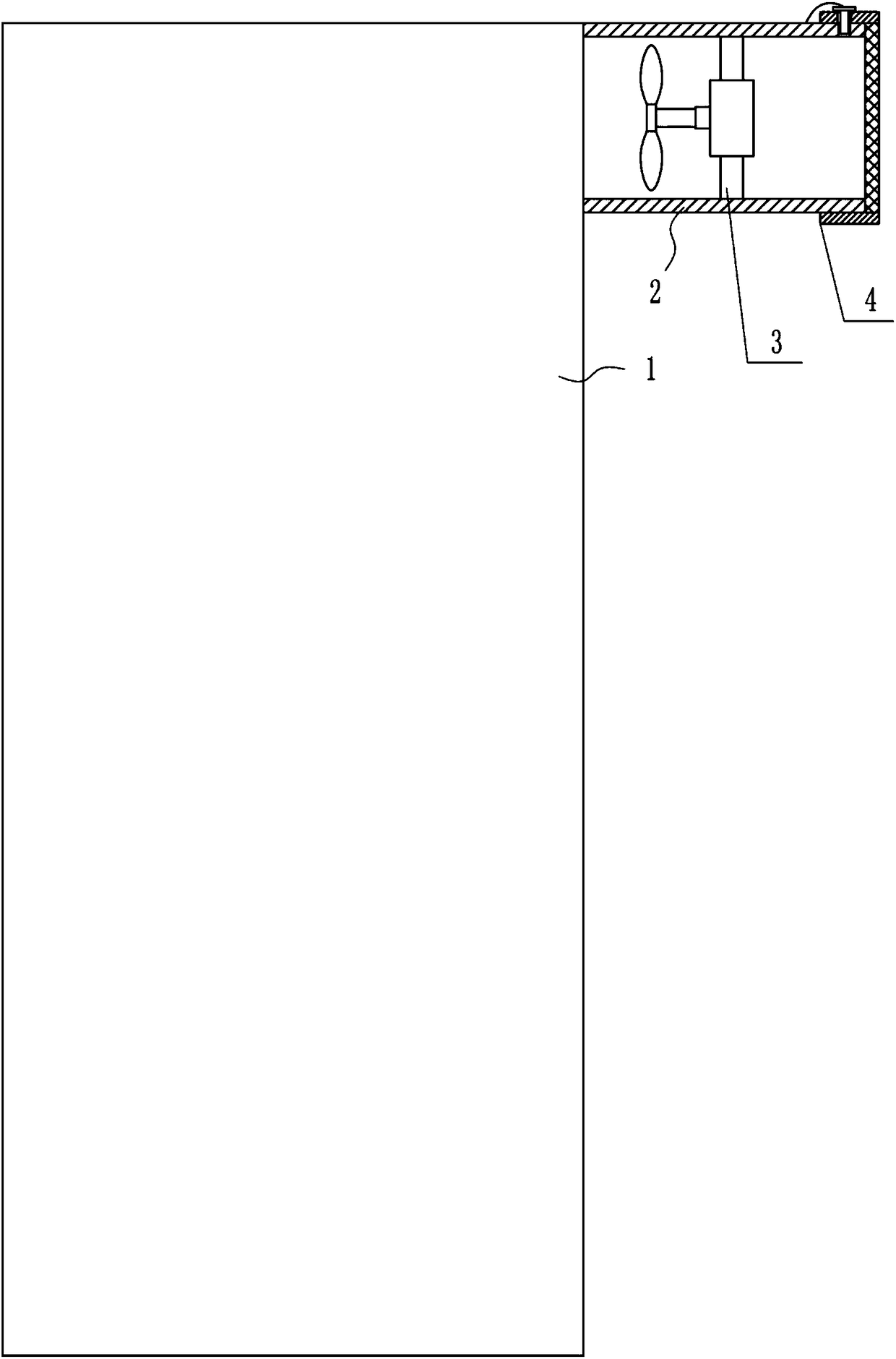
[0028] A switchgear ventilation device, such as Figure 1-4 As shown, it includes a switch cabinet 1, a frame body 2, a blower device 3 and a dustproof device 4. The frame body 2 is installed on the air inlet of the switch cabinet 1, and the middle part of the frame body 2 is provided with a blower device 3. Side is provided with dustproof device 4.

Embodiment 2

[0030] A switchgear ventilation device, such as Figure 1-4 As shown, it includes a switch cabinet 1, a frame body 2, a blower device 3 and a dustproof device 4. The frame body 2 is installed on the air inlet of the switch cabinet 1, and the middle part of the frame body 2 is provided with a blower device 3. Side is provided with dustproof device 4.

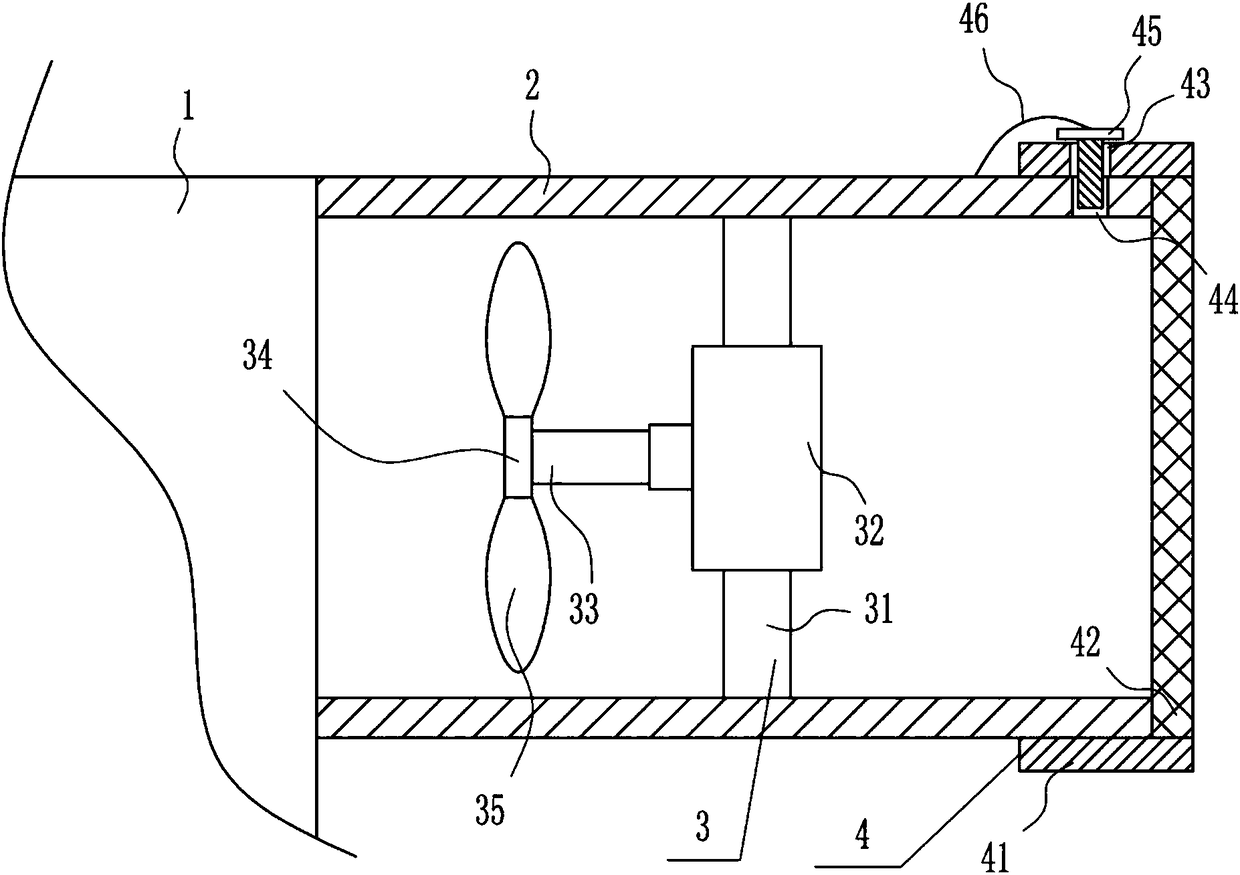
[0031] The blowing device 3 includes a pole 31, a motor 32, a rotating pole 33, a rotating disk 34 and a rotating blade 35, a pole 31 is installed between the middle and the top of the inner bottom of the frame body 2, and a motor 32 is installed horizontally in the middle of the front side of the pole 31. , the output shaft of motor 32 is connected with rotating rod 33 by coupling, and rotating disc 34 is installed on rotating rod 33 left ends, and rotating disc 34 outer surface circumferential direction is equipped with rotating vane 35, and rotating vane 35 is positioned at motor 32 left sides.

Embodiment 3

[0033] A switchgear ventilation device, such as Figure 1-4 As shown, it includes a switch cabinet 1, a frame body 2, a blower device 3 and a dustproof device 4. The frame body 2 is installed on the air inlet of the switch cabinet 1, and the middle part of the frame body 2 is provided with a blower device 3. Side is provided with dustproof device 4.

[0034]The blowing device 3 includes a pole 31, a motor 32, a rotating pole 33, a rotating disk 34 and a rotating blade 35, a pole 31 is installed between the middle and the top of the inner bottom of the frame body 2, and a motor 32 is installed horizontally in the middle of the front side of the pole 31. , the output shaft of motor 32 is connected with rotating rod 33 by coupling, and rotating disc 34 is installed on rotating rod 33 left ends, and rotating disc 34 outer surface circumferential direction is equipped with rotating vane 35, and rotating vane 35 is positioned at motor 32 left sides.

[0035] The dustproof device 4 ...


PUM


Abstract

The invention relates to a ventilating apparatus, particularly a switch cabinet ventilating apparatus, and aims to provide the switch cabinet ventilating apparatus capable of performing ventilating tothe interior of the switch cabinet and with a high ventilating effect and parts not damaged easily in the switch cabinet by solving technical problems. For solving the technical problem, the invention provides the switch cabinet ventilating apparatus, wherein the switch cabinet ventilating apparatus comprises a switch cabinet and the like; a frame body is mounted on the air inlet of the switch cabinet; an air blowing apparatus is arranged in the internal middle part of the frame body; and a dustproof apparatus is arranged on the right side of the frame body. By virtue of a beating apparatus,a filtering plate can be beaten to shake off dust and impurities from the filter plate, so that a condition that the filter plate is accumulated with dust and impurities can be prevented; and throughelectric heating wires, air can be heated, and the interior of the switch cabinet can be ventilated by hot air, so that ventilating to the interior of the switch cabinet and a high ventilating effectcan be achieved, and the parts in the switch cabinet are not damaged easily.

Description

technical field [0001] The invention relates to a ventilation device, in particular to a switch cabinet ventilation device. Background technique [0002] The switch cabinet is a kind of electrical equipment. The outside line of the switch cabinet first enters the main control switch in the cabinet, and then enters the sub-control switch. Each branch is set according to its needs. Such as instruments, automatic controls, motor magnetic switches, various AC contactors, etc., some also have high-voltage room and low-voltage room switch cabinets, high-voltage busbars, such as power plants, etc. load shedding. [0003] In order to ensure the safety of the switchgear, the switchgear will be ventilated to make the switchgear drier, but the general switchgear is not equipped with ventilation devices, and the parts in the switchgear are easily damaged, resulting in the switchgear can not continue to use Therefore, there is an urgent need to develop a switchgear ventilation device t...

Claims


Application Information

Patent Timeline
IPC IPC(8): H02B1/28H02B1/56
CPCH02B1/28H02B1/565
Inventor 刘健红尹新陈梦君
Owner 嘉兴奥腾电子科技有限公司
Why Eureka
Try Eureka