Fire hose cleaning device

A technology of fire hose and cleaning device, applied in fire rescue and other directions, can solve the problems of unclean washing, low manual labor, time-consuming and laborious, etc., and achieve the effect of low manual labor, high cleaning efficiency, and avoiding backlog.

Inactive Publication Date: 2018-09-07
HENAN CHANGMING HANGBIAO ELECTROMECHANICAL EQUIP CO LTD
View PDF0 Cites 5 Cited by
  • Summary
  • Abstract
  • Description
  • Claims
  • Application Information

AI Technical Summary

Problems solved by technology

[0005] The purpose of the present invention is to propose a fire hose cleaning device for the above-mentioned problem that the dirty fire hose after the fire rescue is time-consuming and laborious to clean manually, and is not clean. The fire hose cleaning device has the advantages of simple operation, The advantages of good cleaning effect, high cleaning efficiency and low labor force

Method used


Image

  • Fire hose cleaning device
  • Fire hose cleaning device
  • Fire hose cleaning device

Examples


Embodiment 1

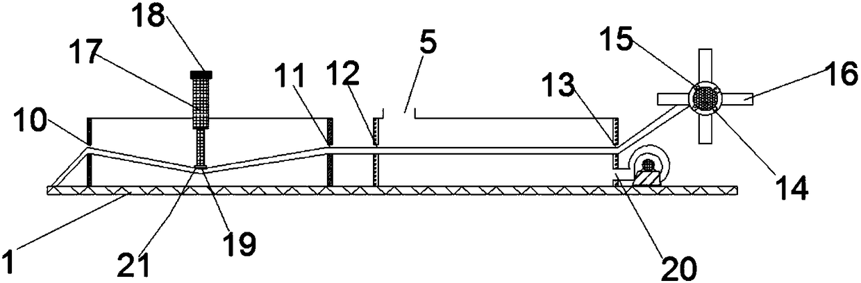
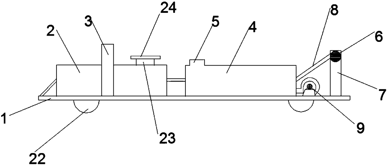
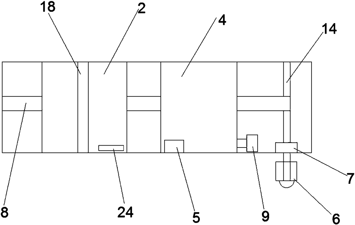
[0032] refer to Figure 1-3 , a fire hose 8 cleaning device, including a base 1, the base 1 is provided with a cleaning tank body 2, a winding mechanism for winding the fire hose after cleaning, the cleaning tank body 2 includes a rectangular tank structure, and the cleaning tank The two opposite side walls of the body 2 are respectively provided with a first through hole 10 and a second through hole 11 for the fire-fighting water pipe to pass through the cleaning tank, and the two sides of the cleaning tank body 2 perpendicular to the first through hole 10 and the second through hole 11 Columns 3 are arranged on both sides, horizontal plates 18 are arranged between the columns 3, telescopic parts 17 are arranged between the horizontal plates 18 and the cleaning tank body 2, one end of the telescopic parts 17 is connected with the horizontal plate 18, and the other end is connected with a pressure rod 21 , the pressing rod 21 is provided with bristles 19 .

[0033] Working pr...

Embodiment 2

[0035] Based on Example 1, with reference to Figure 1-3 , the telescopic member 17 of this embodiment includes an electric telescopic rod.

[0036]When the fire hose 8 needs to be cleaned, the pressure rod 21 connected to the electric telescopic rod can be pushed down by the electric telescopic rod, which is more convenient through electric operation and lower labor force.

Embodiment 3

[0038] Based on Example 1, with reference to Figure 1-3 , the winding mechanism of this embodiment includes a bracket 7 arranged on the base 1, the bracket 7 is provided with a rotating shaft 14, and the rotating shaft 14 is provided with a detachable connecting piece 15 for connecting the winding frame of the fire hose 8, and the rotating shaft 14 is provided with a driving mechanism 6 for driving the rotating shaft 14 to rotate.

[0039] The fire hose 8 winding frame is installed on the rotating shaft 14 through the detachable connector 15, and one end of the fire hose 8 passing through the first through hole 10 and the second through hole 11 is connected to the fire hose 8 winding frame , the rotating shaft 14 is driven to rotate through the driving mechanism 6, so that the fire hose 8 winding frame installed on the rotating shaft 14 is rotated, and then the cleaned fire hose 8 is wound on the fire hose 8 winding frame, which can realize The effect of winding while cleani...


PUM


Abstract

The invention discloses a fire hose cleaning device which comprises a base, wherein a cleaning tank body and a winding mechanism are arranged on the base; the winding mechanism is used for winding a cleaned fire hose; the cleaning tank body comprises a rectangular tank structure; a first through hole and a second through hole used for enabling the fire hose to pass through the cleaning tank are respectively formed in two opposite side walls of the cleaning tank body; upright posts are arranged on two sides of the cleaning tank body perpendicular to the first through hole and the second throughhole; a transverse plate is arranged between the upright posts; a telescopic piece is arranged between the transverse plate and the cleaning tank body; one end of the telescopic piece is connected with the transverse plate, and the other end of the telescopic piece is connected with a pressing rod; and bristles are arranged on the pressing rod. The fire hose cleaning device disclosed by the invention has the advantages of being simple in operation, excellent in cleaning effect, high in cleaning efficiency and low in manual labor.

Description

technical field [0001] The invention relates to the technical field of fire fighting equipment, in particular to a fire hose cleaning device. Background technique [0002] The fire hose is a hose used to transport high-pressure water or foam and other flame-retardant liquids. The traditional fire hose is lined with rubber and the outer surface is wrapped with flax braid. The advanced fire hose is made of polymer materials such as polyurethane. As a result, there are metal joints at both ends of the fire hose, which can be connected to another hose to extend the distance or to a nozzle to increase the liquid spray pressure. [0003] After the fire is rescued, the fire water pipes will be messed up, so the fire water pipes need to be cleaned. [0004] The existing ones are cleaned manually. Manual cleaning is not only time-consuming and laborious, but also not clean. After cleaning, it needs to be folded. Manual folding is not smooth, which will affect the speed of the next u...

Claims


Application Information

Patent Timeline
Patent Type & Authority Applications(China)
IPC IPC(8): A62C33/02A62C33/04
CPCA62C33/02A62C33/04
Inventor 任延超
Owner HENAN CHANGMING HANGBIAO ELECTROMECHANICAL EQUIP CO LTD
Why Eureka
Try Eureka