Method of replacing sliding bearing on weighing arm supporting shaft of ladle turret of continuous casting machine

A technology of ladle turret and sliding bearing, which is applied in casting equipment, casting molten material container, metal processing equipment, etc., can solve the problems of long service life and affecting the safe operation of continuous casting production line, and achieve the reduction of troubleshooting time, Improve construction efficiency and enhance practicability

Active Publication Date: 2018-09-07
MCC5 GROUP CORP SHANGHAI
View PDF8 Cites 4 Cited by
  • Summary
  • Abstract
  • Description
  • Claims
  • Application Information

AI Technical Summary

Problems solved by technology

[0002] The design function of the sliding bearing of the ladle lifting arm of the ladle rotary table and the supporting shaft of the weighing arm of the continuous casting machine is to produce a sliding action when the ladle lifting arm of the ladle rotary table and the weighing arm move slightly, and the design life and service cycle are long, but once damaged It will affect the safe operation of the continuous casting production line; however, the field of on-line replacement of the ladle lifting arm and the supporting shaft sliding bearing of the weighing arm is basically blank at present, which is not expected by those skilled in the art. seen

Method used


Image

  • Method of replacing sliding bearing on weighing arm supporting shaft of ladle turret of continuous casting machine
  • Method of replacing sliding bearing on weighing arm supporting shaft of ladle turret of continuous casting machine
  • Method of replacing sliding bearing on weighing arm supporting shaft of ladle turret of continuous casting machine

Examples


Embodiment Construction

[0055] The present invention will be further described below in conjunction with the accompanying drawings and specific embodiments, but not as a limitation of the present invention.

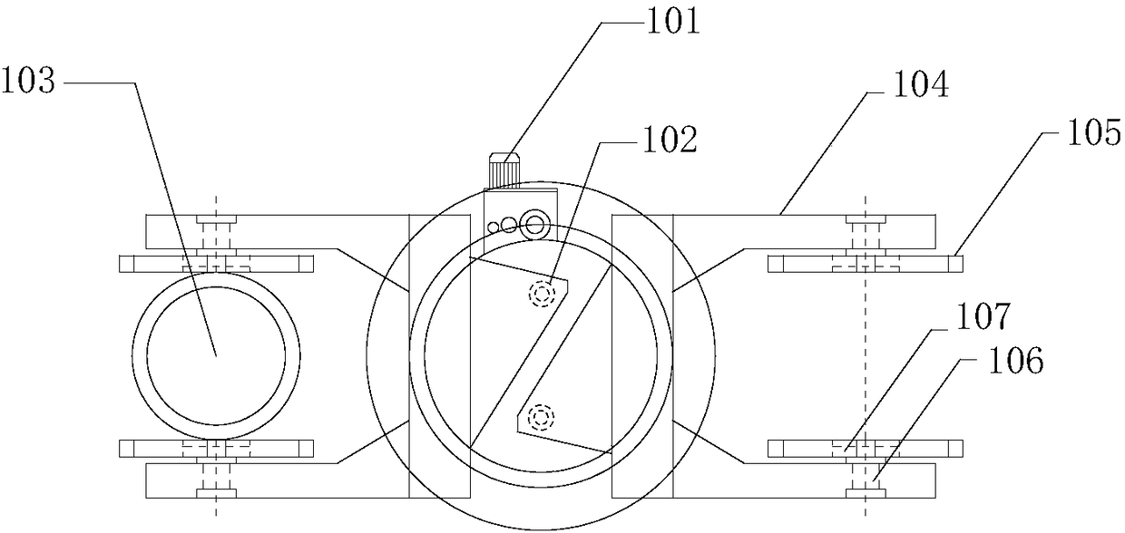
[0056] Such as Figure 1-17As shown, the present invention discloses a method for replacing the sliding bearing on the support shaft of the weighing arm of the ladle turntable of the continuous casting machine. The lifting arm 104 and the weighing arm 105 of the turntable are fixed together by the support shaft 106. Specifically , the method includes the following steps:

[0057] Step S1, after turning the bale turret to the maintenance position and lowering the lifting arm 104 to the lowest position, cut off the hydraulic system and transmission system of the bale turret of the continuous casting machine; that is, to drive the hydraulic pump and the bale turret Motor 101 power failure listing, close lifting arm 104 lifting hydraulic cylinder 102 inlet and outlet oil circuit valve; figure 1 In...


PUM


Abstract

The invention relates to the technical field of continuous casting machine overhauling, in particular to a method of replacing a sliding bearing on a weighing arm supporting shaft of a ladle turret ofa continuous casting machine. The method of replacing the sliding bearing on the weighing arm supporting shaft of the ladle turret of the continuous casting machine comprises the following steps of:pushing out a supporting shaft by using a hydraulic jack so as to separate the supporting shaft from the sliding bearing after using a prefabricated fixed support and a supporting shaft upper-frame tosupport and adjust a supporting arm and a lifting arm, removing the sliding bearing on the weighing arm after moving away the supporting shaft by using a crane in combination with a supporting shaftlifting appliance, and then arranging the sliding bearing to be arranged on the weighing arm, thus realizing the online replacement of the sliding bearing on the weighing arm supporting shaft of the ladle turret of the continuous casting machine. The method of replacing the sliding bearing on the weighing arm supporting shaft of the ladle turret of the continuous casting machine improves the construction efficiency, reduces the time of trouble shooting, further improves the production benefit and has wide market prospect; and auxiliary work fixtures needed by the method are simple and easy toobtain and has very strong practicability.

Description

technical field [0001] The invention relates to the technical field of maintenance of continuous casting machines, in particular to a method for replacing a sliding bearing on a support shaft of a weighing arm of a ladle turntable of a continuous casting machine. Background technique [0002] The design function of the sliding bearing of the ladle lifting arm of the ladle rotary table and the supporting shaft of the weighing arm of the continuous casting machine is to produce a sliding action when the ladle lifting arm of the ladle rotary table and the weighing arm move slightly, and the design life and service cycle are long, but once damaged It will affect the safe operation of the continuous casting production line; however, the field of on-line replacement of the ladle lifting arm and the supporting shaft sliding bearing of the weighing arm is basically blank at present, which is not expected by those skilled in the art. seen. Contents of the invention [0003] In vie...

Claims


Application Information

Patent Timeline
Patent Type & Authority Applications(China)
IPC IPC(8): B22D41/13
CPCB22D41/13
Inventor 张占美
Owner MCC5 GROUP CORP SHANGHAI
Why Eureka
Try Eureka