Clamp for processing holes

A technology for machining holes and fixtures, which is applied in the direction of manufacturing tools, metal processing equipment, metal processing machinery parts, etc., can solve the problems of unguaranteed drilling processing quality, waste of time for clamping and unloading, low processing efficiency, etc., and achieve good results. Promotion of use value, fast and accurate positioning, and reasonable structure

Inactive Publication Date: 2018-09-07
XINCHANG COUNTY YULIN STREET WEIBO MACHINERY FACTORY
View PDF0 Cites 5 Cited by
  • Summary
  • Abstract
  • Description
  • Claims
  • Application Information

AI Technical Summary

Problems solved by technology

This kind of processing method not only has low processing efficiency and high labor intensity, but also cannot guarantee the quality of drilling processing, and a lot of time is wasted in clamping and unloading of workpieces.

Method used


Image

  • Clamp for processing holes
  • Clamp for processing holes
  • Clamp for processing holes

Examples


Embodiment Construction

[0019] The following will clearly and completely describe the technical solutions in the embodiments of the present invention with reference to the accompanying drawings in the embodiments of the present invention. Obviously, the described embodiments are only some, not all, embodiments of the present invention.

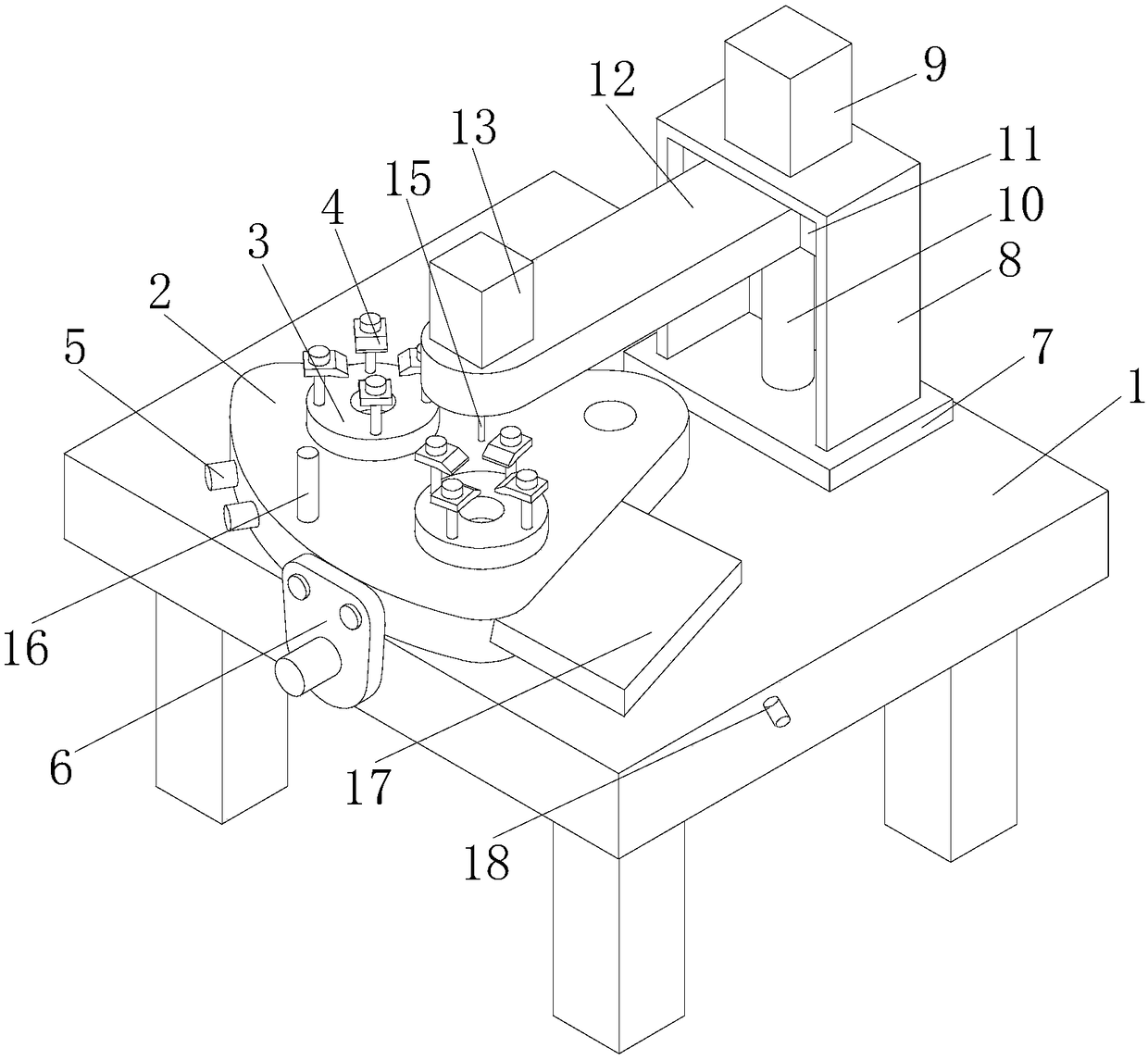
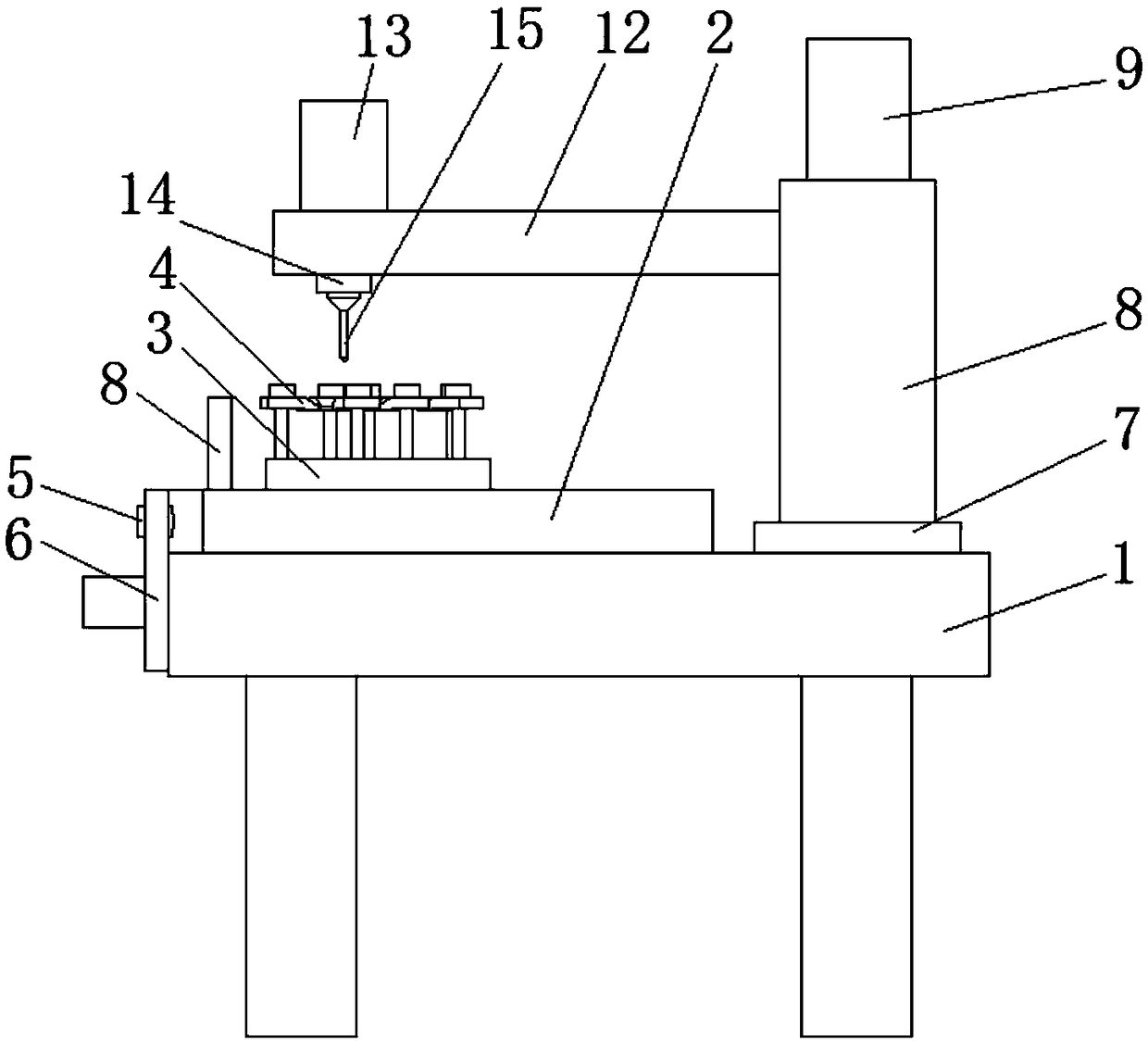
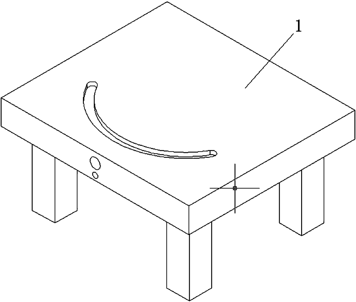
[0020] refer to Figure 1-6 , a fixture for machining holes, comprising a workbench 1, a fan-shaped block 2 is connected to the top surface of the workbench 1, the fan-shaped block 2 is a fan-shaped structure, the bottom surface of one end corresponding to the fan-shaped central angle of the fan-shaped block 2 is provided with a rotating shaft, and the fan-shaped block 2 is connected to the workbench 1 through the rotating shaft. The bottom surface of the sector block 2 is provided with an arc-shaped sliding bar, and the top surface of the workbench 1 is provided with an arc-shaped chute. The arc-shaped slide bar is embedded in the arc-shaped chute. The sector block ...


PUM


Abstract

The invention discloses a clamp for processing holes. The clamp comprises a workbench, wherein a fan-shaped block is connected on the top surface of the workbench; a clamping device is mounted on thetop surface of the fan-shaped block; the clamping device comprises a fixed base which is fixedly arranged on the top surface of the fan-shaped block; a plurality of pressure plates which are distributed in the form of an array are connected on the top surface of the fixed base; a pin roll is arranged on the side surface of the fan-shaped block; a baffle block is connected between the pin roll andthe side surface of the workbench; a base is fixedly arranged on the top surface of the workbench; a bracket is fixedly arranged on the top surface of the base; a first drive motor is mounted on the top of the bracket; the bottom output end of the first drive motor is connected with a lead screw; a nut block sleeves outside the lead screw; and the side surface of the nut block is fixedly equippedwith a cantilever. The two sides of the fan-shaped block are equipped with protectors, and the two ends of an arc-shaped slide slot are equipped with joints, so that the device can be protected. The clamp can realize continuous link between mutual and quick switching-fixing and processing of two stations, greatly improves production efficiency, and is reasonable in structure.

Description

technical field [0001] The invention relates to the technical field of drilling processing equipment, in particular to a jig for processing holes. Background technique [0002] The hole processing generally uses a small drilling machine to fix the workpiece by hand, or clamp the workpiece in the fixture, and then manually operate the feeding mechanism of the drilling tool to drill the workpiece. After the drilling is completed, the workpiece is unloaded. Next, reinstall the workpiece and drill the holes. This kind of processing method not only has low processing efficiency and high labor intensity, but also cannot guarantee the quality of drilling processing, and a lot of time is wasted in clamping and unloading of workpieces. For this reason, we propose a jig for machining holes to solve the above problems. Contents of the invention [0003] The object of the present invention is to propose a jig for machining holes in order to solve the shortcomings in the prior art. ...

Claims


Application Information

Patent Timeline
Patent Type & Authority Applications(China)
IPC IPC(8): B23B47/00B23Q1/66B23Q3/06
CPCB23B47/00B23Q1/66B23Q3/06
Inventor 梁美旭
Owner XINCHANG COUNTY YULIN STREET WEIBO MACHINERY FACTORY
Why Eureka
Try Eureka