
Integrally-formed arc type milling cutter

An arc and integrated technology, which is applied in the field of arc milling cutters, can solve the problems of lack of cooling devices, etc., achieve the effects of convenient use, avoiding the decrease of structural stability, and improving the service life

Inactive Publication Date: 2018-09-07
常州苏德工具有限公司
View PDF0 Cites 2 Cited by
  • Summary
  • Abstract
  • Description
  • Claims
  • Application Information

AI Technical Summary

Problems solved by technology

[0004] The object of the present invention is to provide an integrally formed arc milling cutter in order to solve the problem that the above-mentioned existing arc milling cutter lacks a cooling device

Method used


Image

  • Integrally-formed arc type milling cutter
  • Integrally-formed arc type milling cutter
  • Integrally-formed arc type milling cutter

Examples


Embodiment 1

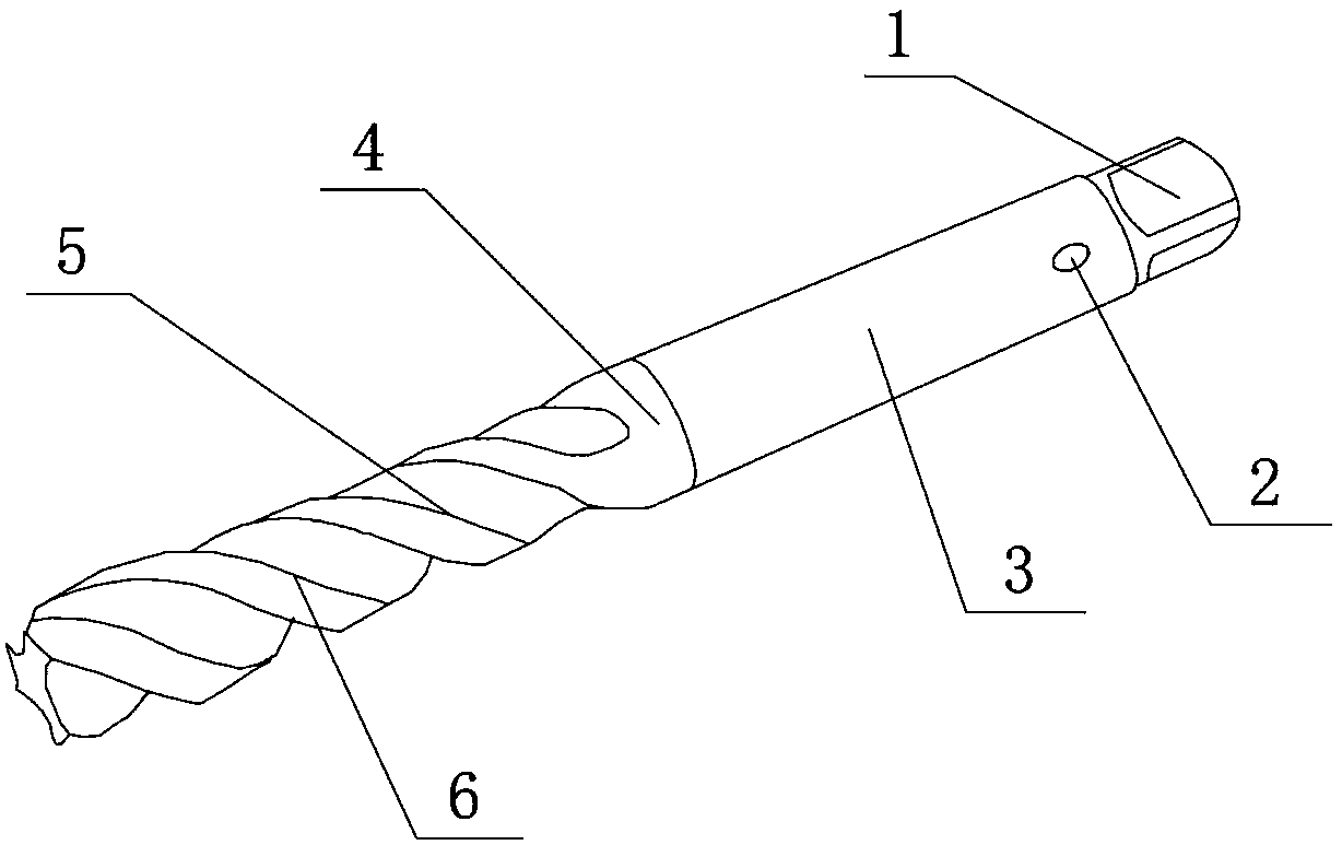
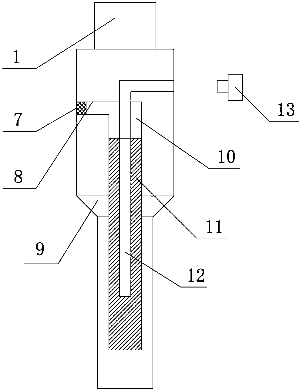
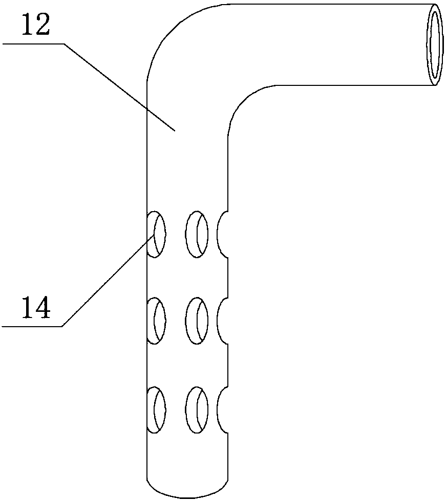
[0021] see Figure 1-4 As shown, an integrally formed arc type milling cutter includes a working head 4, a connecting block 9 is arranged at one end of the working head 4, a connecting rod 3 is arranged at one end of the connecting block 9, and a connecting head 1 is arranged at one end of the connecting rod 3, and the working head 4 is formed by The spiral groove 5 and the cutting edge 6 are composed of a groove 10 inside the connecting rod 3, a sponge layer 11 is arranged inside the groove 10, and an air outlet 8 is arranged on one side of the groove 10, that is, the circular arc milling cutter is discharged through the air outlet 8, and then It can reduce the internal pressure of the arc-type milling cutter, thereby avoiding the decrease of the structural stability of the arc-type milling cutter due to excessive internal pressure of the arc-type milling cutter. Catheter 12, one end of the catheter 12 is provided with a liquid inlet 2, the inside of the liquid inlet 2 is cov...

Embodiment 2

[0023] read on Figure 1-4 , the difference from Example 1 is that the groove 10 runs through the connecting rod 3, the connecting block 9 and the working head 4, and the groove 10 is closely connected with the sponge layer 11, so that the cooling liquid in the sponge layer 11 can be round The arc milling cutter plays the role of cooling. The cover 13 is threadedly connected to the liquid inlet 2 , and the shape of the catheter 12 is L-shaped, thereby preventing external dust from entering the catheter 12 from the liquid inlet 2 . The shape of the connecting block 9 is a truncated cone, and the connecting block 9 is fixedly connected with the connecting rod 3 and the working head 4, so that the stress concentration between the working head 4 and the connecting rod 3 can be reduced, and the circle can be improved. The service life of the arc milling cutter. The helical grooves 5 and the cutting edges 6 are alternately arranged, and the direction of rotation of the cutting edg...


PUM


Abstract

The invention discloses an integrally-formed arc type milling cutter. The milling cutter comprises a connecting head, a liquid inlet, a connecting rod, a work head, a spiral groove, a cutting edge, adustproof net, an air outlet, a connecting block, a groove, a sponge layer, a liquid guide pipe, a sealing cover and a liquid outlet; the milling cutter has the beneficial effects that the sealing cover is unscrewed from the interior of the liquid inlet, cooling liquid is poured into the liquid guide pipe from the liquid inlet, the sealing cover covers the interior of the liquid inlet, exterior dust can be prevented from entering the liquid guide pipe through the liquid inlet, cooling liquid in the liquid guide pipe enters the sponge layer through the liquid outlet, the sponge layer can absorbthe cooling liquid, the arc type milling cutter is arranged on a knife rest through the connecting head, when the arc type milling cutter cuts a workpiece, a large amount of heat absorbed by the arctype milling cutter can be absorbed by the cooling liquid in the sponge layer, the arc type milling cutter is actively cooled, and the service life of the arc type milling cutter can be prolonged.

Description

technical field [0001] The invention relates to an arc type milling cutter, in particular to an integrally formed arc type milling cutter, which belongs to the application field of mechanical processing. Background technique [0002] A milling cutter is a rotating tool with one or more teeth for milling. When working, each knife tooth cuts off the allowance of the workpiece intermittently in turn. Milling cutters are mainly used for machining planes, steps, grooves, forming surfaces and cutting off workpieces on milling machines. [0003] However, there are still certain defects in the existing arc-type milling cutters in use. The existing arc-type milling cutters generally cut metal when in use, and then the arc-type milling cutters will heat up in a short time , and then if the arc-type milling cutter is not cooled, the service life of the arc-type milling cutter will be reduced, and the existing arc-type milling cutter lacks a cooling device. Contents of the invention...

Claims


Application Information

Patent Timeline
IPC IPC(8): B23C5/28
CPCB23C5/28
Inventor 薛成新李锦
Owner 常州苏德工具有限公司
Learn More