
Autonomous underwater vehicle capable of separating payloads

An underwater vehicle, the technology of the aircraft, applied in the directions of underwater ships, underwater operation equipment, ships, etc., can solve the problems of reducing the endurance of the aircraft, unable to achieve long-range deployment, and increasing the sailing resistance, etc. The separation process is safe and reliable, reducing the risk of collision and reducing the effect of sailing resistance

Pending Publication Date: 2018-09-07
CHINA JILIANG UNIV
View PDF5 Cites 12 Cited by
  • Summary
  • Abstract
  • Description
  • Claims
  • Application Information

AI Technical Summary

Problems solved by technology

At present, the main deployment methods of underwater vehicle loads are as follows. For example, the method of explosive bolt + rotating shaft is used. This method requires that one end of the load is disconnected and separated after turning to a specific angle range. This method is difficult to control, and After separation, the load has a certain rotational angular velocity, which is easy to collide with the carrier and cannot sink in a relatively stable attitude; However, blunt bosses are formed on the front and rear end surfaces of the separated load compartment, which will increase the navigation resistance, reduce the endurance of the aircraft, and cannot achieve long-range deployment.

Method used


Image

  • Autonomous underwater vehicle capable of separating payloads
  • Autonomous underwater vehicle capable of separating payloads
  • Autonomous underwater vehicle capable of separating payloads

Examples


Embodiment Construction

[0022] The embodiments of the present invention will be described in detail below in conjunction with the accompanying drawings, so that the advantages and features of the invention can be more easily understood by those skilled in the art, so as to define the protection scope of the present invention more clearly.

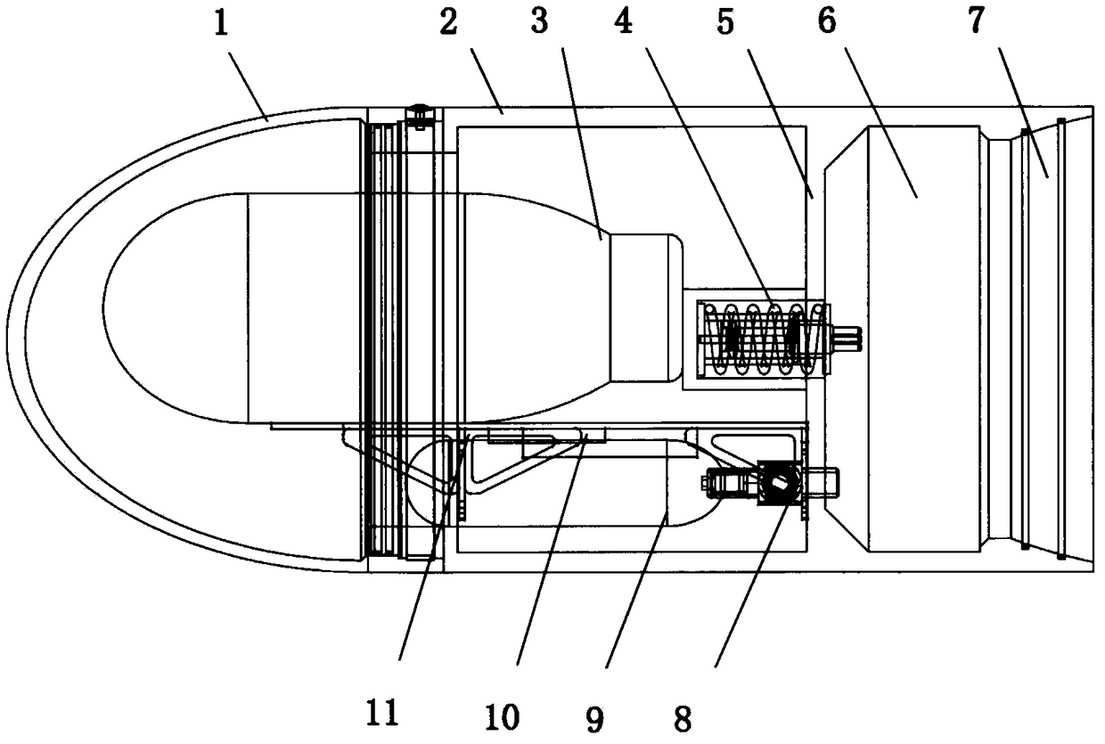
[0023] Such as figure 1 , figure 2 As shown, the detachable load compartment I is fixed to the bow of the aircraft body II before deployment. Such as image 3 , Figure 6 As shown, the shell head shell 1 of the load compartment I is detachable, and is firmly connected with the rear shell 2 through an internal connection structure. The inner connecting structure includes an inner connecting ring 14 arranged on the end of the rear shell 2 close to the head shell 1. The outer diameter of the inner connecting ring 14 is equal to the inner diameter of the outer ring end of the head shell 1 and is sleeved in the head shell 1. , the inner connecting ring 14 is provi...


PUM


Abstract

The invention relates to an autonomous underwater vehicle capable of separating payloads. The autonomous underwater vehicle capable of separating the payloads comprises an underwater vehicle body, anunderwater vehicle payload bay and a separating device. The payload bay comprises a shell, a separating device and a payload; and the separating device consists of a pneumatic system and a spring separator. According to the autonomous underwater vehicle capable of separating the payloads, by using a vacuum mode, the end part of the payload bay is connected with the bow of the underwater vehicle body by means of the difference between internal and external pressures at the connected part of the payload bay body; and therefore, the structure with the connecting mode is simple and reliable. Whenthe autonomous underwater vehicle moves to a payload laying area, the pneumatic system of the separating device is started, the vacuum environment at the connected part of the payload bay body is released, and the difference between the internal and external pressures is reduced; and after the difference between the internal and external pressures reaches a separating threshold, the spring separator ejects out of the payload bay. The separating device can rapidly separate the payload bay, the attitude of the separating device is stable, and the separating device is uneasy to collide with the underwater vehicle body; and therefore, payload laying safety and stability of the autonomous underwater vehicle are enhanced, and higher practical significance is realized.

Description

technical field [0001] The invention belongs to the technical field of underwater vehicles, and in particular relates to an autonomous underwater vehicle capable of separating loads and completing load deployment. Background technique [0002] The ocean contains abundant resources, which play a vital role in the development of human beings. As an important means of exploring the ocean, the main role of autonomous underwater vehicles is as a diving equipment and carrier for humans to conduct comprehensive inspections and research on the ocean. Research and complete a variety of assignments. In the military field, autonomous underwater vehicles can carry different types of functional loads, such as mines, detectors, underwater prefabricated weapons, etc., and carry out concealed deployment in predetermined areas to complete monitoring or strike tasks. At present, the main deployment methods of underwater vehicle loads are as follows. For example, the method of explosive bolt ...

Claims


Application Information

Patent Timeline
Patent Type & Authority Applications(China)
IPC IPC(8): B63G8/00
CPCB63G8/00B63G2008/004
Inventor 严天宏宋金梁何波
Owner CHINA JILIANG UNIV
Learn More