
Battery labeling equipment

A device and battery technology, applied in the directions of labeling, labeling machines, labels, etc., can solve the problems affecting the neatness of label sticking, labeling instability, battery deformation, etc., to ensure neatness, improve stability, and enhance fit. The effect of firmness

Pending Publication Date: 2018-09-07
贵州鸿兴时代动力新能源科技有限公司
View PDF0 Cites 3 Cited by
  • Summary
  • Abstract
  • Description
  • Claims
  • Application Information

AI Technical Summary

Problems solved by technology

However, when the labeling roller is used to paste the label, the battery will move relative to the labeling roller, resulting in unstable labeling and wrinkles; when using the labeling pole for labeling, the labeling pole will stick the label while moving in the vertical direction On the battery, but because the labeling rod exerts a certain pressure on the battery, it will cause a certain degree of slight deformation of the battery; whether the labeling roller or the labeling rod is used for labeling, due to the difference in the technical proficiency of the operator, the position of the battery is different. The angle will be different, which directly affects the tidiness of label pasting

Method used


Image

  • Battery labeling equipment
  • Battery labeling equipment

Examples


Embodiment Construction

[0015] Further detailed explanation through specific implementation mode below:

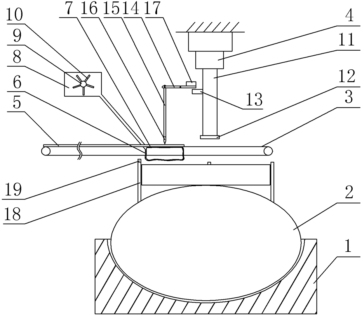
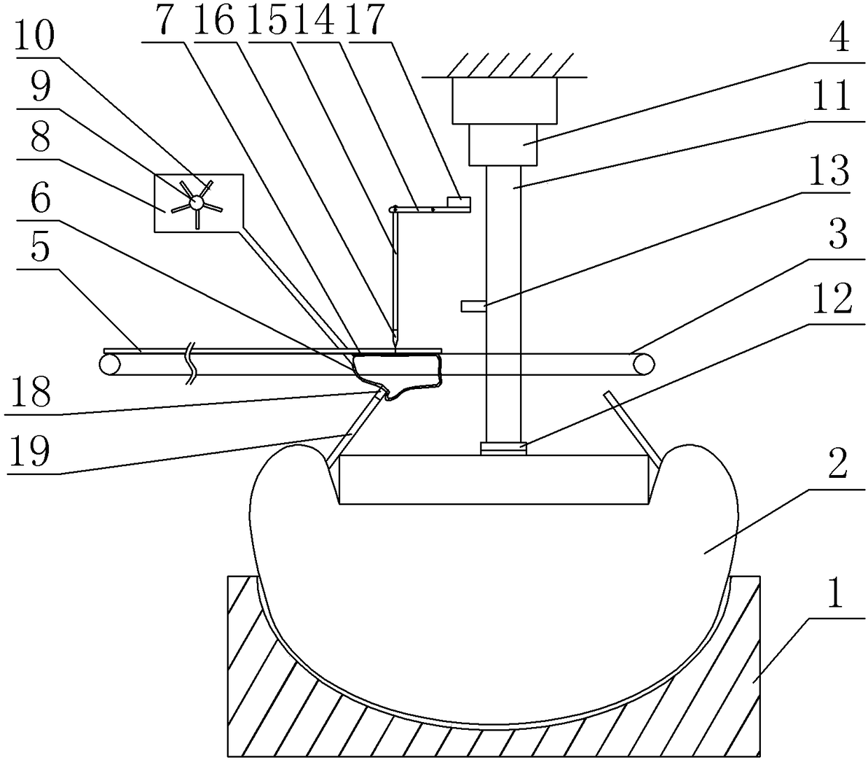
[0016] The reference signs in the accompanying drawings of the description include: support table 1, air bag 2, first conveyor belt 3, cylinder 4, label 5, plastic bag 6, hole 7, glue filling box 8, round roller 9, stirring block 10, sticker Marking rod 11, labeling plate 12, touch block 13, first connecting rod 14, second connecting rod 15, cutting knife 16, weight block 17, positioning rod 18, extruding plate 19.

[0017] Such as figure 1 , 2 The battery labeling equipment shown includes a support table 1 , an air bag 2 , a first conveyor belt 3 , a second conveyor belt, a cutting mechanism and an air cylinder 4 from bottom to top. The first conveyor belt 3 and the second conveyor belt are arranged side by side on the frame, the first conveyor belt 3 is located in front of the second conveyor belt, and the first conveyor belt 3 and the second conveyor belt are transmitted from left to right. ...


PUM


Abstract

The invention relates to the field of labeling, in particular to battery labeling equipment. The battery labeling equipment comprises a support table, an air bag, two conveyor belts, a cylinder and acutting mechanism, wherein a glue holding bag is arranged on a rack, and a plurality of pores communicated with the inside of the glue holding bag are formed in the upper surface of the glue holding bag; a labeling rod is fixed on an output shaft of the cylinder; the cutting mechanism comprises a trigger block, a first connecting rod, a second connecting rod and a cutting knife, the middle of thefirst connecting rod is hinged to the rack, one end of the first connecting rod is hinged to one end of the second connecting rod, the second connecting rod is glidingly connected with the rack, and the other end of the second connecting rod is fixedly connected with the cutting knife; the trigger block is fixedly arranged on the output shaft of the cylinder, can be contacted with the other end ofthe first connecting rod and pushes the first connecting rod to rotate; the air bag is arranged on the support table, a plurality of positioning rods are fixed on the surface of the air bag, and partof the positioning rods can be contacted with and squeeze the glue holding bag. With adoption of the technical scheme, stability and regularity of battery labeling can be improved, and a battery cannot be deformed in the labeling process.

Description

technical field [0001] The invention relates to the field of labeling, in particular to battery labeling equipment. Background technique [0002] In order to distinguish the source of products and services and guide consumers to recognize the brand for shopping or consumption, more and more battery manufacturers will attach their own company LOGO and other labels to the battery. At present, the commonly used labeling equipment is a labeling machine, which is a device that sticks the label on the specified position of the battery through a labeling roller or a labeling rod. [0003] As electronic products become smaller and thinner, their LOGO and other labels also become more delicate, and it is usually necessary to accurately position the label. However, when the labeling roller is used to paste the label, the battery will move relative to the labeling roller, resulting in unstable labeling and wrinkles; when using the labeling pole for labeling, the labeling pole will sti...

Claims


Application Information

Patent Timeline
Patent Type & Authority Applications(China)
IPC IPC(8): B65C9/06B65C9/18B65C9/22B65C9/36B65C1/02
CPCB65C1/02B65C9/06B65C9/1803B65C9/2256B65C9/36B65C2009/1834B65C2009/0075
Inventor 金璇陈兴奎黎标
Owner 贵州鸿兴时代动力新能源科技有限公司
Learn More