Method or device for taking-out and shape-forming of coil

A technology for taking out devices and coils, which is applied in coil manufacturing, electromechanical devices, electric components, etc., and can solve problems such as coil deformation, coils that cannot reach the specified size, and prolonging production time.

Inactive Publication Date: 2009-09-23
NIPPON SERBIG
View PDF4 Cites 6 Cited by
  • Summary
  • Abstract
  • Description
  • Claims
  • Application Information

AI Technical Summary

Problems solved by technology

[0007] (2) Coil deformation
Therefore, most of the coils cannot reach the specified size, and post-processing such as reheating in the furnace is required
And, especially in high-strength wires, it is easy to produce twisted and twisted coils
[0009] (3) Production time
This further extends the production time

Method used


Image

  • Method or device for taking-out and shape-forming of coil
  • Method or device for taking-out and shape-forming of coil
  • Method or device for taking-out and shape-forming of coil

Examples


Embodiment Construction

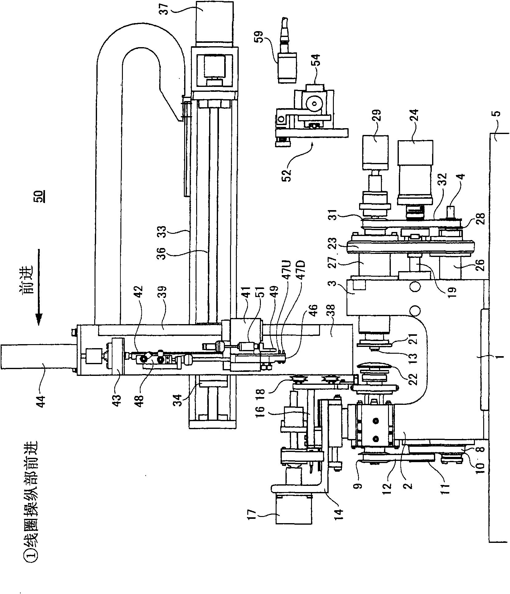
[0127] Hereinafter, the present invention will be described in detail based on the illustrated embodiment examples. figure 1 It is a front view of the coil forming apparatus 50 which concerns on embodiment of this invention. In addition, in this device 50, the structure of the winding machine part is described in detail in, for example, Japanese Patent Application Laid-Open No. 2005-116657, Japanese Patent Laid-Open No. 2001-358029 and Japanese Patent Laid-Open No. 10 related to the application of the present inventor. - Bulletin No. 304628, etc. Therefore, only the parts considered to be necessary for the description of the embodiment example will be described here.

[0128] figure 1 It is the front of embodiment example 50. 1 is the main shaft body, which is arranged on the casing 5, the left side of which is provided with the left side of the main shaft body 2 (fixed side), and the right side is provided with the right side of the main shaft body 3 (movable side). At th...


PUM


Abstract

A high accuracy of a size in the production of a track shape coil and a rectangular shape bobbinless coil is realized. At the same time, the alignment of the coil and a tact time are also improved. [MEANS FOR SOLVING THE PROBLEMS] A winding tool is provided with a winding core (13) slidably disposed at one portion (21) of the winding tool. The winding core (13) is energized toward the other portion (22) of the winding tool. Coil receiving pins (47U, 47D) are provided opposite to the winding core (13) and the one portion (21) of the winding tool is moved to a side of coil handling member (46). The coil receiving pins (47U, 47D) push the winding core (13) backward. A coil (56) moves from the winding core (13) to the coil receiving pins (47U, 47D). The receiving pins (47U, 47D) to receive and support the coil (56) are made apart from each other so that the coil (56) expands. Press tools (53L, 53R) movable in a direction intersecting the expanding direction press the coil (56) at the same time as the expansion or before or after it. A digital camera (59) then picks up an image of the coil (56). A coil contour obtained from the digital camera (59) is compared with a target value. An expanding amount and a pressing amount are adjusted in accordance with a difference between them.

Description

technical field [0001] The present invention relates to a method or device for taking out and forming coils, in particular to a method or device for taking out and forming ideal coils suitable for manufacturing racetrack (elliptic) and rectangular air-core coils. Background technique [0002] When winding (winding) a racetrack-shaped or rectangular air-core coil, a winding mandrel with the same racetrack-shaped or rectangular section as the finished product shape of the coil has been used in the past. A wire is wound thereon to obtain an air-core coil having a desired shape (for example, refer to Patent Document 1). [0003] Patent Document 1: Japanese Patent Application Laid-Open No. 2003-168618 [0004] However, these past methods have the following problems: [0005] (1) Neatness [0006] In the conventional method, the entry position of the wire rod is near the junction of the straight part of the coil and the R part (deflection part). Here is a position where inters...

Claims


Application Information

Patent Timeline
Patent Type & Authority Applications(China)
IPC IPC(8): H01F41/04B21F3/04H02K15/04
Inventor 大野冨士夫佐佐木幸喜长山和彦
Owner NIPPON SERBIG
Why Eureka
Try Eureka