High-speed elevator compensation rope tensioning device

A tensioning device, a technology for high-speed elevators, applied in the field of elevator components, can solve the problems of large space occupation of elevator shaft bottom pits, increased structural complexity, unfavorable manufacturing and assembly, etc., and achieves convenient manufacturing, simplified structure, and guaranteed safety. Effect

Pending Publication Date: 2018-09-07
SUZHOU LAIYIN ELEVATOR CO LTD
View PDF2 Cites 2 Cited by
  • Summary
  • Abstract
  • Description
  • Claims
  • Application Information

AI Technical Summary

Problems solved by technology

But this CN204528997U following shortcoming: one, because it respectively connects a main girder at the left end and the right end of sub-beam, respectively connects the upper end of a guide rail at the two ends of two main girders, the lower end of guide rail is fixed with installation base plate, in two main girders A damping buffer is connected to the middle of the beam, so there are two main beams, four guide rails, and two damping buffers, which significantly increases the co

Method used


Image

  • High-speed elevator compensation rope tensioning device
  • High-speed elevator compensation rope tensioning device

Examples


Embodiment Construction

[0019] In order to understand the technical essence and beneficial effects of the present invention more clearly, the applicant will describe in detail the following examples, but the descriptions of the examples are not intended to limit the solutions of the present invention. Equivalent transformations that are only formal but not substantive should be regarded as the scope of the technical solution of the present invention.

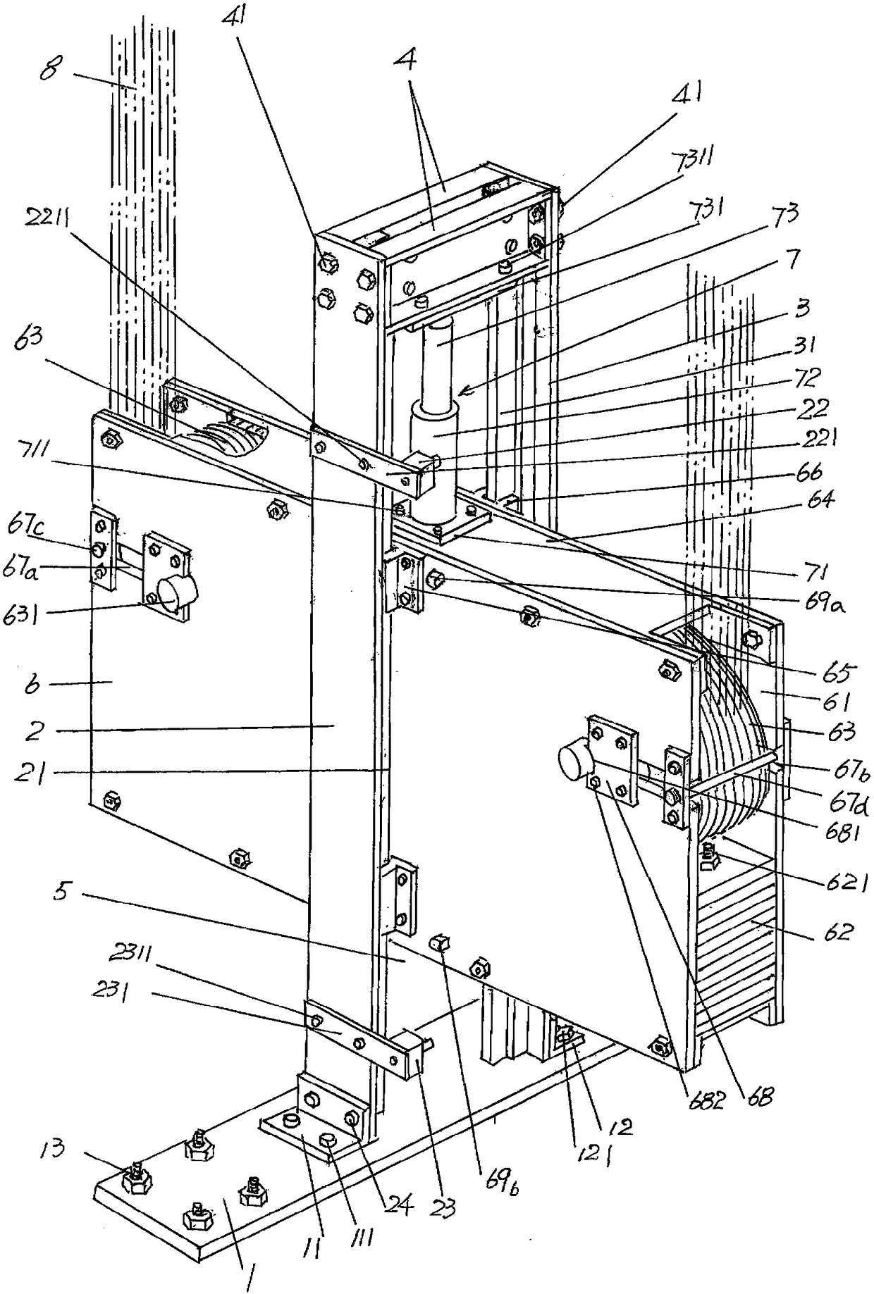
[0020] In the following descriptions, all concepts related to directionality or orientation of up, down, left, right, front and rear are based on figure 1 The position status shown is an example, so it cannot be understood as a special limitation on the technical solution provided by the present invention.

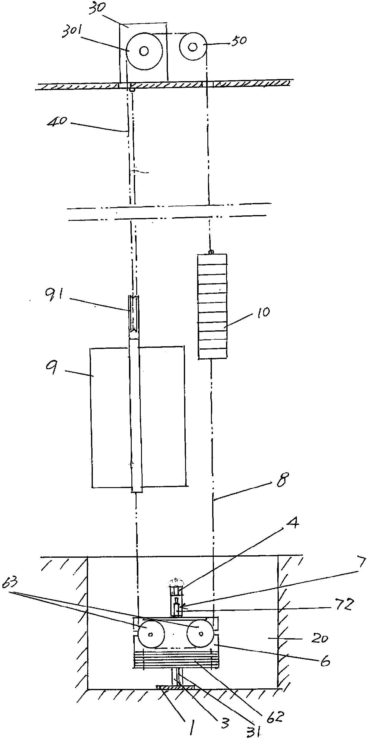
[0021] See figure 1 , shows a rectangular and elongated installation base plate 1, which is fixed to the elevator hoistway pit 20 ( figure 2shown), that is fixed to the bottom surface of the elevator shaft pit 20; a front guide rail 2 and a rear...


PUM


Abstract

The invention discloses a high-speed elevator compensation rope tensioning device. The device comprises a mounting bottom plate, a front guide rail, a rear guide rail, a guide wheel box, a damping buffering mechanism and a group of compensation ropes; the mounting bottom plate is fixed at the bottom of an elevator shaft pit; the middle of the guide wheel box in the length direction is simultaneously in direct sliding fit with the front guide rail and the rear guide rail at the position of a receding cavity of the guide wheel box, a plurality of counterweight plates are arranged at the lower part of a guide wheel box cavity in the length direction of the guide wheel box cavity in an overlapped state, and compensation rope wheels are arranged at the positions, corresponding to the positionsabove the counterweight plates, at the left end and the right end of the guide wheel box cavity correspondingly; the part, located at the position corresponding to the position of the middle of a guide rail connecting cross beam, of the damping buffering mechanism is arranged on a guide wheel box top plate of the guide wheel box and is connected with the middle of the side, which faces downwards,of the guide rail connecting plate; and one ends of the group of compensation ropes are connected with the lower part of a car, the middle parts of the group of compensation ropes sleeve the compensation rope wheels, and the other ends of the group of compensation ropes are connected with a counterweight block. According to the device, the structure is simplified, and manufacturing and assemblingare convenient; the space occupation of the elevator shaft pit is reduced; and the safety is guaranteed.

Description

technical field [0001] The invention belongs to the technical field of elevator components, and in particular relates to a high-speed elevator compensating rope tensioning device. Background technique [0002] The aforementioned high-speed elevator means that the running speed of the elevator car is above 6m / s. Because the rope swing (rope throwing) phenomenon often occurs during the operation of the elevator car, that is, the swaying phenomenon of the traction wire rope occurs. The swaying of the traction wire rope will affect the running stability of the elevator car and even cause failure. Therefore, according to the design specifications, for Vertical up and down elevators with a running speed of the elevator car greater than 3m / s are usually equipped with a compensation rope, which balances the weight of the traction wire rope. In order to make the compensation rope run stably under the condition of guidance, the elevator compensation rope tensioning device is generall...

Claims


Application Information

Patent Timeline
IPC IPC(8): B66B7/10
CPCB66B7/10
Inventor 李力李云波张维皓
Owner SUZHOU LAIYIN ELEVATOR CO LTD
Why Eureka
Try Eureka