Cutter holder mounting structure and cutter holder joint

A technology of installation structure and tool holder, which is applied in glass cutting devices, manufacturing tools, glass manufacturing equipment, etc., can solve the problem of inability to obtain high-precision and high-quality products, and achieves suppression of inclined driving or position deviation, elimination of looseness, The effect of accurate processing

Inactive Publication Date: 2018-09-07
MITSUBOSHI DIAMOND IND CO LTD
View PDF1 Cites 2 Cited by
  • Summary
  • Abstract
  • Description
  • Claims
  • Application Information

AI Technical Summary

Problems solved by technology

In this way, when the cutter wheel deviates obliquely at the initial stage of scribing, in the subsequent driving, even if it returns to straight driving due to the caster effect, it will still be as smooth as possible. Figure 8 As shown in the figure, the scribed line S3 deviated by the distance Z from the predetermined planned scribing line S is formed, and a high-precision and high-quality product cannot be obtained.

Method used


Image

  • Cutter holder mounting structure and cutter holder joint
  • Cutter holder mounting structure and cutter holder joint
  • Cutter holder mounting structure and cutter holder joint

Examples


Embodiment Construction

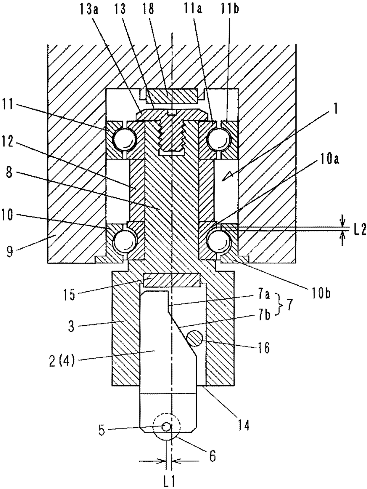
[0050] Hereinafter, the mounting structure of the tool post of the present invention will be described in detail. A part of the installation structure of the tool post of the present invention includes a Figure 5 ~ Figure 7The structural elements of the same function as the conventional tool holder mounting structure shown. Therefore, the same reference numerals will be attached to the parts having the same functions for description.

[0051] like figure 1 As shown, the tool post mounting structure 1 of the present invention includes a tool post 2 and a tool post joint 3 for holding the tool post 2 . The tool holder 2 has a substantially columnar main body 4 , and a cutter wheel 6 is rotatably attached to the lower end of the main body 4 via an axle 5 perpendicular to the axis of the main body 4 .

[0052] In addition, an attachment portion 7 for positioning when attached to the tool holder joint 3 is provided on the upper portion of the main body portion 4 . The attachme...


PUM


Abstract

The present invention provides a cutter holder mounting structure capable of preventing a cutter holder from being obliquely displaced at the initial stage of scribing and capable of accurately forming a scribe line. The revolving shaft (8) of the cutter holder mounting structure (1) having a cutter wheel (6) at the lower end is rotatably mounted on the scribing head (9) of a scribing device (A) via a ball bearing (10). The outer ring (10b) of the ball bearing (10) is mounted on the scribing head (9) or a portion connected to the scribing head (9), and the inner rings (10a, 11a) of the ball bearings (10, 11) are mounted on the revolving shaft (8). A magnet (18) that always sucks and lifts the revolving shaft (8) and the inner rings upward together is disposed above the revolving shaft (8),thereby suppressing the looseness of the cutter holder mounting structure (1) caused by the internal clearance (L2) of the ball bearing (10).

Description

technical field [0001] The present invention relates to a tool holder mounting structure and a tool holder joint for installing a tool holder holding a cutter wheel (also called a scribing wheel) on a scribing head of a scribing device. Used for scribe line (grooving) for surface machining and cutting. Background technique [0002] In the past, in the process of cutting a brittle material substrate such as a glass substrate, the following method is generally known: a cutter wheel is pressed against the surface of the substrate to form a plurality of scribe lines in the X-Y direction orthogonal to each other, and then, along the scribe line The wire applies an external force from the back side to bend the substrate, thereby cutting the unit substrate. For example, Patent Document 1 discloses such a method. [0003] The cutter wheel is mounted to the scribing head of the scribing device via a tool holder for use. Figure 5 ~ Figure 7 The existing tool holder and the installat...

Claims


Application Information

Patent Timeline
Patent Type & Authority Applications(China)
IPC IPC(8): C03B33/027
CPCC03B33/027C03B33/033C03B33/105Y02P40/57
Inventor 冈岛康智地主贵裕龟井慎太郎阪口良太
Owner MITSUBOSHI DIAMOND IND CO LTD
Why Eureka
Try Eureka