
A bridge inspection vehicle slewing device

A technology of bridge inspection vehicle and slewing device, which is applied in the direction of bridges, bridge construction, bridge parts, etc. It can solve the problems of low reliability of rotation connection, damage of slewing bearing, shaking of lower truss, etc., and achieves simple structure, reduced bearing pressure, and easy Achieved effect

Active Publication Date: 2019-06-14
JIANGSU ZHONGLU ENG DETECTION CO LTD
View PDF4 Cites 0 Cited by
  • Summary
  • Abstract
  • Description
  • Claims
  • Application Information

AI Technical Summary

Problems solved by technology

Only the slewing bearing is supported, which not only easily leads to the damage of the slewing bearing, but also easily leads to the shaking of the lower truss.

Method used


Image

  • A bridge inspection vehicle slewing device
  • A bridge inspection vehicle slewing device
  • A bridge inspection vehicle slewing device

Examples


Embodiment 1

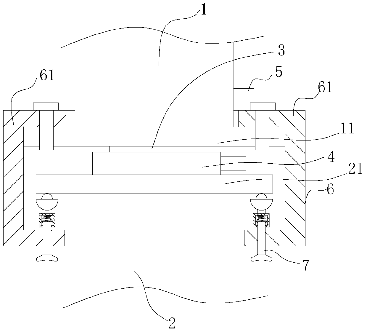
[0025] refer to figure 1 , the swivel device of the bridge inspection vehicle includes: an upper truss 1, a lower truss 2 and a driving mechanism 5, a bearing seat 3 arranged below the upper truss 1, a revolving base 4 arranged above the lower truss 2, the revolving base 4 and the bearing seat 3 Through the connection of the slewing bearing arranged in the bearing seat 3, the drive mechanism 5 is connected with the lower truss 2 in transmission to drive the lower truss 2 to rotate. In addition, the swivel device of the bridge inspection vehicle also includes: a fixed sleeve 6 and a plurality of support assemblies 7;

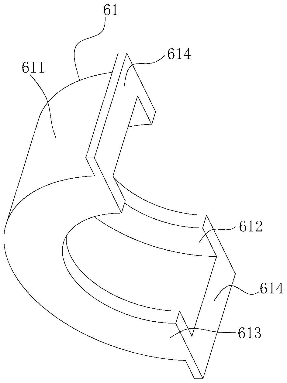
[0026] refer to figure 1 and image 3 , the upper truss 1 is provided with a mounting plate 11, the lower truss 2 is provided with a support plate 21, and the lower surface of the support plate 21 is a plane; the fixed sleeve 6 includes two semi-cylindrical parts 61, and the semi-cylindrical part 61 includes: semi-cylindrical 611 , a semi-annular first protrus...

Embodiment 2

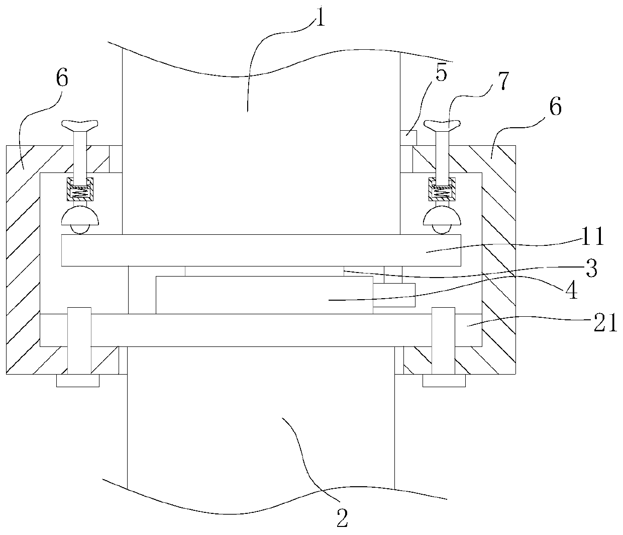
[0036] refer to figure 2 , the swivel device of the bridge inspection vehicle includes: an upper truss 1, a lower truss 2 and a driving mechanism 5, a bearing seat 3 arranged below the upper truss 1, a revolving base 4 arranged above the lower truss 2, the revolving base 4 and the bearing seat 3 Through the connection of the slewing bearing arranged in the bearing seat 3, the drive mechanism 5 is connected with the lower truss 2 in transmission to drive the lower truss 2 to rotate. In addition, the swivel device of the bridge inspection vehicle also includes: a fixed sleeve 6 and a plurality of support assemblies 7;

[0037] The upper truss 1 is provided with a mounting plate 11, and the lower truss 2 is provided with a support plate 21. The upper surface of the mounting plate 11 is a plane; the fixing sleeve 6 includes two semi-cylindrical parts 61, and the semi-cylindrical part 61 includes: a semi-cylindrical cylinder 611, A semi-annular first protrusion 612 disposed at th...


PUM


Abstract

The invention discloses a slewing device for a bridge detection vehicle. The slewing device for the bridge detection vehicle comprises an upper truss, a lower truss, a driving mechanism, a fixing sleeve and a plurality of supporting assemblies; a mounting plate is arranged on the upper truss; a supporting plate is arranged on the lower truss; the fixing sleeve comprises two semicircular cylinder pieces; mounting parts of the two semicircular cylinder pieces are fixedly connected via bolts; first projections of the semicircular cylinder pieces are fixed above the mounting plates, each supporting assembly is mounted on any second projection by using a respective mounting screw rod, and a universal wheel of each supporting assembly abuts against the lower surface of the supporting plate; or the second projections of the semicircular cylinder pieces are both fixed below the supporting plate, each supporting assembly is mounted on any first projection by using a respective mounting screw rod, and the universal wheel of each supporting assembly abuts against the upper surface of the mounting plate. Through adoption of the technical scheme, the pressure borne on a slewing bearing is reduced so that the rotational connection between the upper truss and the lower truss is firmer.

Description

technical field [0001] The invention belongs to the technical field of bridge detection, and in particular relates to a turning device of a bridge detection vehicle. Background technique [0002] The bridge inspection vehicle is a special equipment in the field of bridge inspection technology. Specifically, it is a special vehicle that can provide a working platform for bridge inspection personnel during the inspection process, is equipped with bridge inspection instruments, and is used for mobile inspection and / or maintenance operations. [0003] At present, on the bridge inspection vehicle, the upper truss and the lower truss are rotationally connected through a slewing mechanism, and the lower truss is mainly supported by the slewing bearing in the slewing mechanism, and the slewing bearing has a relatively high bearing strength. Only the slewing bearing is supported, which not only easily leads to the damage of the slewing bearing, but also easily leads to the shaking of...

Claims


Application Information

Patent Timeline
Patent Type & Authority Patents(China)
IPC IPC(8): E01D19/10
CPCE01D19/106
Inventor 杨响孙雪伟
Owner JIANGSU ZHONGLU ENG DETECTION CO LTD
Learn More