Rotor, motor comprising rotor and power device comprising motor

A technology for power devices and rotors, applied in the direction of electromechanical devices, magnetic circuit rotating parts, electric components, etc., can solve the problems of increased motor torque ripple, decreased reluctance torque, and large reluctance, so as to reduce the rotational speed. Torque ripple, the effect of increasing the reluctance torque

Active Publication Date: 2018-09-07
NIPPON DENSAN CORP
View PDF5 Cites 2 Cited by
  • Summary
  • Abstract
  • Description
  • Claims
  • Application Information

AI Technical Summary

Problems solved by technology

like figure 1 As shown, in the existing synchronous reluctance motor 10, each air gap 13 of the electromagnetic steel plate 12 constituting the rotor 11 has the same width in the radial direction of the motor, or the width gradually decreases from the radially inner side to the radially outer side (not shown ), resulting in an increase in the torque ripple of the motor, thereby suppressing the reluctance torque of the motor and affecting the practicability of the motor
[0004] and, if figure 1 and figure 2 As shown, in the direction of the d-axis, the width of the electromagnetic steel plate 12 between the two radially innermost air gaps 13 decreases from the radially inner side to the radially outer side, that is, A
As a result, the reluctance difference between the reluctance in this region and the flux barrier is reduced, thereby reducing the reluctance torque

Method used


Image

  • Rotor, motor comprising rotor and power device comprising motor
  • Rotor, motor comprising rotor and power device comprising motor
  • Rotor, motor comprising rotor and power device comprising motor

Examples


Embodiment 1

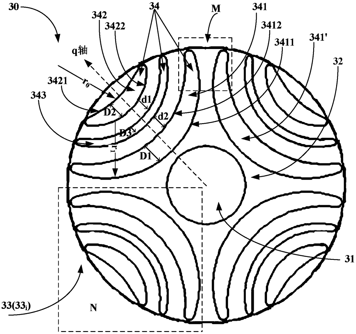
[0035] An embodiment of the present invention provides a rotor, image 3 It is a plan view of the rotor of Example 1 of the present invention. Since the rotor is composed of electromagnetic steel plates laminated in the axial direction, it can be seen from image 3 What you see is the axial side of an electromagnetic steel plate.

[0036] Such as image 3 As shown, the rotor 30 is located on the outer periphery of the rotating shaft 31 of the motor (not shown), and rotates together with the rotating shaft 31. The rotor 30 is composed of electromagnetic steel plates 32 laminated in the axial direction. The through-hole group 33 of the steel plate 32, the through-hole group 33 has a plurality of through-holes 34, and the plurality of through-holes 34 have an imaginary line extending in the radial direction as a center line (such as image 3 The shown q-axis) is in the shape of an arc extending to both sides of the q-axis and radially outward, and a plurality of through holes 3...

Embodiment 2

[0060] The embodiment of the present invention also provides a motor, Figure 6 It is an exploded schematic diagram of the motor of Embodiment 2 of the present invention.

[0061] Such as Figure 6 As shown, the motor 60 can have a rotating shaft 31, and the rotating shaft 31 extends along the central axis; a rotor 30, which is the rotor as described in Embodiment 1, and the rotor 30 rotates around the rotating shaft 31; and a stator 62, assembled , the stator 62 is opposed to the rotor 30 in the radial direction. Since the structure of the rotor 30 has been described in detail in Embodiment 1, its content is included here, and will not be repeated here.

[0062] In this embodiment, in order to further reduce the torque ripple, there is a certain corresponding relationship between the slots of the stator of the motor and the through holes of the electromagnetic steel plate constituting the rotor.

[0063] Figure 7 It is a top view of a part of the motor of Embodiment 2 of...

Embodiment 3

[0068] The embodiment of the present invention also provides a power device, which has the motor described in Embodiment 2. Since the main structure of the motor has been described in detail in Embodiment 2, its content is included here. I won't repeat them here.

[0069] In this embodiment, as mentioned above, the power device can be any device equipped with a motor, and the motor can be applied to the power transmission of a bulldozer or a crawler belt of a power shovel as a power device.

[0070] According to the structure of the motor of the power plant of this embodiment, the difference in reluctance between the electromagnetic steel sheets constituting the rotor of the motor can be enlarged, thereby increasing the reluctance torque and reducing the torque ripple.


PUM


Abstract

The embodiment of the invention provides a rotor, a motor comprising the rotor and a power device comprising the motor. The rotor is located at the periphery of a rotating shaft of the motor and rotates together with the rotating shaft. The rotor is composed of electromagnetic steel plates laminated in the axial direction, each electromagnetic steel plate is provided with a through hole group penetrating through the electromagnetic steel plate in the axial direction, the through hole group has a plurality of through holes, and the plurality of through holes take an imaginary line extending inthe radial direction as a center line and are in an arc shape extending towards two sides and the radial outer side of the center line. In addition, the plurality of through holes are arranged in theradial direction, wherein the curvature radius of the arc-shaped surface, which is located at the radial inner side, of the through hole at the radial inner most side in the plurality of through holesis the minimum, and/or the curvature radius of the arc-shaped surface, which is located at the radial outer side, of the through hole at the radial outer most side in the plurality of through holes is the maximum. According to the structure of the rotor, the reluctance difference between the electromagnetic steel plates forming the rotor can be enlarged, so that the reluctance torque is increased, and the torque ripple is reduced.

Description

technical field [0001] The invention relates to the field of motors, in particular to a rotor, a motor including the rotor, and a power device including the motor. Background technique [0002] In the rotor of a synchronous reluctance motor, there are many through holes in the middle of the electromagnetic steel plate that constitutes the rotor. These through holes form an air gap called a flux barrier. These air gaps cause a difference in reluctance. When the motor is supplied with current, Reluctance torque is generated due to the difference in reluctance. [0003] figure 1 is a schematic diagram of the air gap of the electromagnetic steel plate constituting the rotor in the prior art; figure 2 is in the prior art figure 1 Enlarged view of dashed box P shown. Wherein, it is defined that the direction in which the magnetic flux is easy to travel in the rotor is the direct axis (d axis), and the direction in which the magnetic flux is difficult to travel is the horizont...

Claims


Application Information

Patent Timeline
Patent Type & Authority Applications(China)
IPC IPC(8): H02K1/22
CPCH02K1/22H02K2213/03H02K1/246H02K19/103H02K29/03
Inventor 颜圣展徐豫伟颜国智林信男王国珉刘承宗
Owner NIPPON DENSAN CORP
Why Eureka
Try Eureka