A Magnetic Channel Estimation Method Based on Near Field Positioning

A magnetic channel and near-field technology, applied in channel estimation, near-field transmission systems, baseband system components, etc., can solve the problems of large amount of calculation and narrow application area, and achieve the effect of simplifying the magnetic channel estimation method

Active Publication Date: 2021-02-23
NANJING UNIV
View PDF4 Cites 0 Cited by
  • Summary
  • Abstract
  • Description
  • Claims
  • Application Information

AI Technical Summary

Problems solved by technology

[0004] Among the existing estimation methods, the method (1) needs to observe the voltage and current of all transmitting coils, and the calculation amount is relatively large; the method (2) needs to establish a communication feedback circuit, and the application area is relatively narrow

Method used


Image

  • A Magnetic Channel Estimation Method Based on Near Field Positioning
  • A Magnetic Channel Estimation Method Based on Near Field Positioning
  • A Magnetic Channel Estimation Method Based on Near Field Positioning

Examples


Embodiment Construction

[0043] The content of the present invention will be further described in detail below in conjunction with the accompanying drawings.

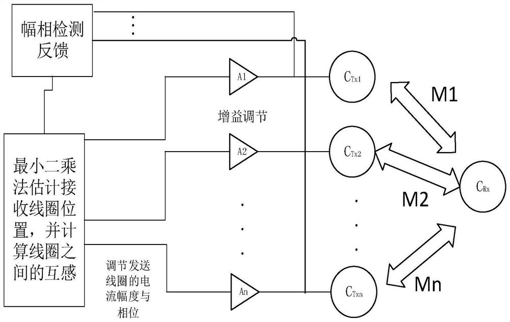
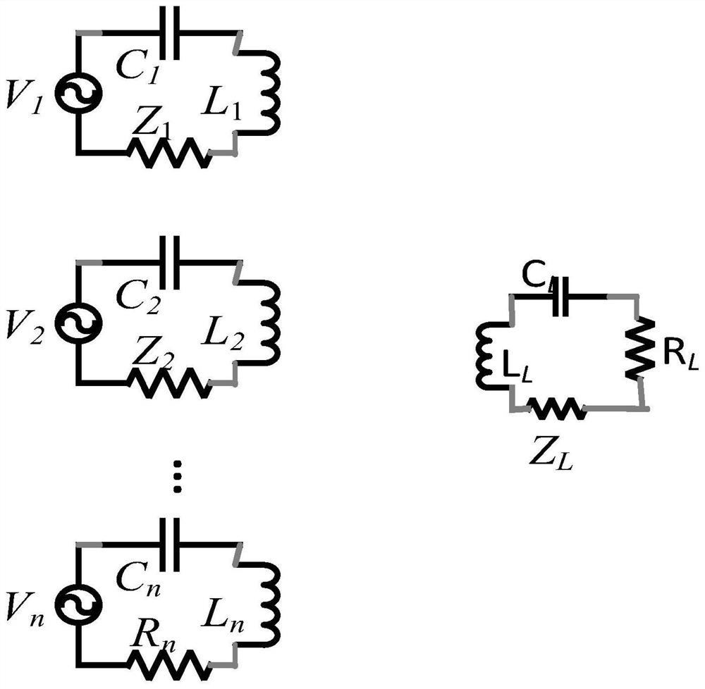
[0044] The wireless energy transfer system we consider is as figure 1 Shown is a multi-send-single-receive system working in a resonance state in the near field. Such as figure 2 As shown, the left side is the transmitting coil array, and the right side is the receiving coil. When establishing the circuit model diagram, in order to simplify the analysis, the cross-coupling between the coils is ignored, and only the direct coupling between the two coils is considered. It can be seen from the figure that the sending coil loop parameter is L 1 , L 2 ···L n , C 1 、C 2 ···C n , R 1 , R 2 ···Rn . R L is the system equivalent load, V 1 , V 2 ···V n For the excitation power supply. Because the system works in a resonant state, in the experiment we need to tune the sending and receiving coils and have the same operating frequency of 1MH...


PUM


Abstract

The present invention discloses a magnetic channel estimation method based on near-field positioning, which includes the following steps: in the present invention, there are M sending coils and 1 receiving coil, and 3 sending coils are selected, and the 3 sending coils are loaded with a fixed Frequency AC signal, observe the current and voltage values ​​on the three sending coils in turn, use the least square method to estimate the magnetic field strength between each sending coil and receiving coil, and then estimate the position of the receiving coil; use the estimated position to calculate other sending coils The mutual inductance between the coil and the receiving coil; thereby adjusting the amplitude and phase of the voltage or current on the sending coil, and finally making the energy transmitted to the receiving coil with high efficiency. The invention enables the system to maximize the receiving power of the receiving end under the premise of satisfying the energy constraint of the sending end.

Description

technical field [0001] The invention belongs to the field of wireless communication, and in particular relates to a magnetic channel estimation method based on near-field positioning. Background technique [0002] With the progress of society and the development of technology, our daily life is increasingly dependent on many personal mobile devices, such as mobile phones, tablets and wearable devices. While every device can make life more convenient, we must remember to charge these devices every day, which is a constant and growing burden. If these devices could be charged wirelessly, it would alleviate this everyday anxiety and greatly reduce the number of different chargers required. The main advantage of wireless charging technology is its convenience and versatility. By adopting wireless charging technology, public mobile device charging stations will become a reality. The disadvantage is that the efficiency of wireless charging is somewhat lower than that of wired ch...

Claims


Application Information

Patent Timeline
Patent Type & Authority Patents(China)
IPC IPC(8): H04B5/00H04L25/02
CPCH04B5/0025H04B5/0037H04B5/0043H04L25/0202Y02D30/70
Inventor 唐岚陆建峰明强
Owner NANJING UNIV
Why Eureka
Try Eureka