Vacuum preparing device and application method

A technology of vacuum batching and batching barrels, applied in mixing methods, chemical instruments and methods, mixers with rotating stirring devices, etc., can solve the problems of poor mixing effect, easy introduction of impurities, air bubbles, etc., achieve uniform batching, improve circulation Use performance, anti-deposition effect

Pending Publication Date: 2018-09-11
SUZHOU AONITE SILICON CARBIDE CERAMIC TECH CO LTD
View PDF2 Cites 1 Cited by
  • Summary
  • Abstract
  • Description
  • Claims
  • Application Information

AI Technical Summary

Problems solved by technology

The device uses screw stirring under normal atmospheric pressure environment, the stirring effect is poor, and it is easy to introduce impurities, air bubbles, etc.

Method used


Image

  • Vacuum preparing device and application method
  • Vacuum preparing device and application method
  • Vacuum preparing device and application method

Examples


Embodiment 1

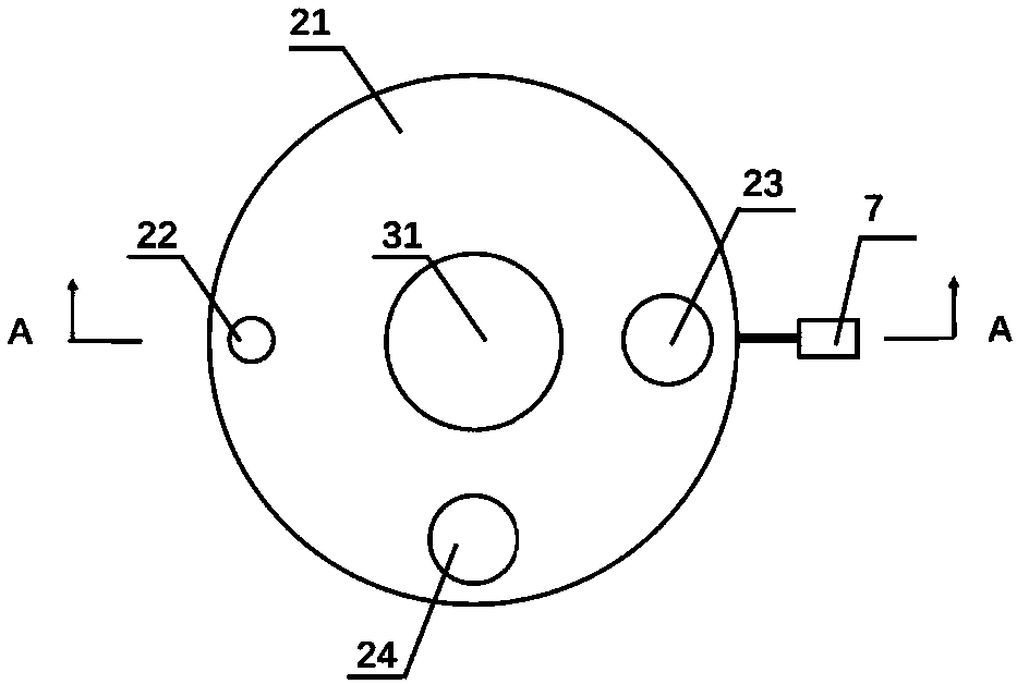
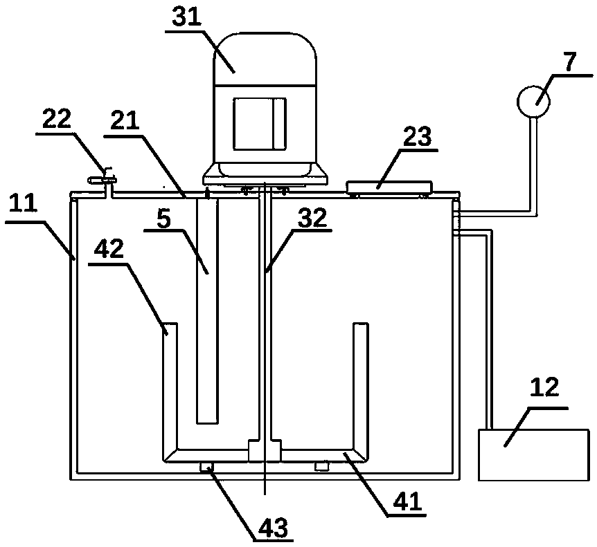
[0053] like figure 1 , 2 As shown, a vacuum batching device includes a cylinder body 11 and a cylinder head 21, the cylinder head 21 covers the top of the cylinder body, a cavity is formed between the cylinder body 11 and the cylinder head 21, and the cylinder body 11 and the cylinder body Cover 21 is separable between the two, which is convenient for dismounting. A seal is provided on the contact surface between the cylinder body 11 and the cylinder head 21 to ensure the sealing performance. One side of the cylinder body 11 is sealed and connected to the vacuum pump 12 for vacuuming. The upper surface of the cylinder head 21 is provided with a valve 22. When the valve 22 is opened, the cavity communicates with the external atmosphere, and when the valve 22 is closed, the cavity is isolated from the external atmosphere, thereby forming an airtight seal. The environment enables the batching process to be carried out in a vacuum environment, which is conducive to improving the...

Embodiment 2

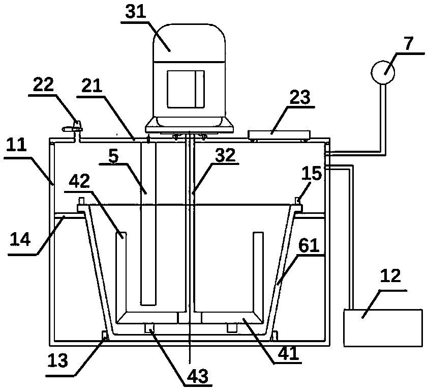
[0069] like image 3 As shown, the difference between this embodiment and Embodiment 1 is that a batching bucket 62 is set inside the cylinder body 11, a groove 13 is set at the bottom of the cylinder body 11, and the bottom of the batching bucket 61 is snapped into the concave In slot 13. The stirring paddle 41 , the first sub-stirring paddle 42 , the second sub-stirring paddle 43 , and the stirring blocking part 5 are all accommodated in the batching barrel 61 . By arranging the batching barrel 62 inside the cylinder 11, the raw materials can be placed in the batching barrel 62 for stirring, and the bottom of the batching barrel 62 is clamped with the bottom of the cylinder 11, and is arranged as a detachable structure, so the batching barrel 62 is replaceable. When the batching barrel 62 is used for a long time or the proportion of raw materials needs to be changed, the batching barrel 62 can be replaced to avoid mutual influence between raw materials with different propor...


PUM


Abstract

The invention discloses a vacuum preparing device and an application method. The vacuum preparing device comprises a cylinder body and a cylinder cover, a sealing piece is arranged on the contact facebetween the cylinder body and the cylinder cover, one side of the cylinder body is connected with a vacuum pump, and the mode is used for achieving the vacuum environment of the preparing device. A motor is arranged on the cylinder cover, a rotating shaft of the motor penetrates through the cylinder cover, extends into a cavity, and is connected with a stirring paddle, and the stirring paddle extends in the direction of the side edge of the cylinder body and is used for stirring raw materials. A stirring stopping part is also arranged on the cylinder cover, and the stirring evenness of raw materials is improved. The application method of the vacuum preparing device includes the following steps that 1, the motor is started; 2, the raw materials are put into the preparing device; 3, the cylinder cover covers the cylinder body, and the vacuum pump is started; 4, the raw materials are fully stirred; 5, the motor is stopped; 6, a valve is started; 7, the prepared raw materials are taken out.

Description

technical field [0001] The invention relates to a mixing device, in particular to a vacuum batching device and a using method. Background technique [0002] The batching of raw materials is one of the key steps in the preparation of ceramic materials. If the batching is uneven, it will lead to uneven ceramics after molding, and cracks are prone to appear. If impurities, air bubbles, etc. are introduced during the batching process, defects will also be introduced into the finished product, resulting in a decrease in product performance and affecting the use effect. At present, the ceramic raw materials in the industry use hand-held stirring rods or ordinary screw-type mixing drums to manually stir the ceramic raw materials to be mixed under normal atmospheric pressure. The ingredients are not uniform, and impurities and air bubbles are easily introduced. [0003] Chinese invention patent CN201510462601.9 discloses a ceramic billet mixing equipment, including a mixing chamber...

Claims


Application Information

Patent Timeline
Patent Type & Authority Applications(China)
IPC IPC(8): B01F7/18B01F13/06B01F3/00B01F23/00
CPCB01F23/09B01F27/112B01F33/70B01F27/90
Inventor 梁士城
Owner SUZHOU AONITE SILICON CARBIDE CERAMIC TECH CO LTD
Why Eureka
Try Eureka