
Heavy torque logical encoder detection machine

An encoder and logic technology, which is applied in the field of heavy torque logic encoder detection machine, can solve the problems of increased occupied volume, complicated machine, troublesome screening process, etc., and achieves the effect of rapid screening, improved efficiency and reasonable structure

Pending Publication Date: 2018-09-11
广东钺河智能科技有限公司
View PDF16 Cites 0 Cited by
  • Summary
  • Abstract
  • Description
  • Claims
  • Application Information

AI Technical Summary

Problems solved by technology

[0002] In the traditional encoder production process, after the encoder is assembled, it needs to be inspected to test the quality of the encoder and improve the yield rate of the shipment. If the static inspection can only detect the instantaneous signal of the encoder, it cannot be completely The entire working condition of the encoder is detected. If dynamic detection is used, the encoder shaft needs to be rotated to test the complete working condition of the encoder.
However, in the existing testing machines, the rotating motor that drives the shaft of the encoder cannot be connected to the shaft quickly and stably, and the rotating motor cannot drive the shaft of the encoder well, especially for testing heavy-torque logic encoders, because The damping of the shaft rotation of the heavy torque logic encoder is larger than that of the ordinary encoder. If the driving end of the rotating motor cannot be stably connected to the encoder shaft, the angle of rotation of the shaft will not be enough to complete the test. The working condition of the encoder
In addition, after the encoder of the existing detection machine is tested for good or bad, it needs a manipulator to take out the defective products and then unload them.

Method used


Image

  • Heavy torque logical encoder detection machine
  • Heavy torque logical encoder detection machine
  • Heavy torque logical encoder detection machine

Examples


Embodiment Construction

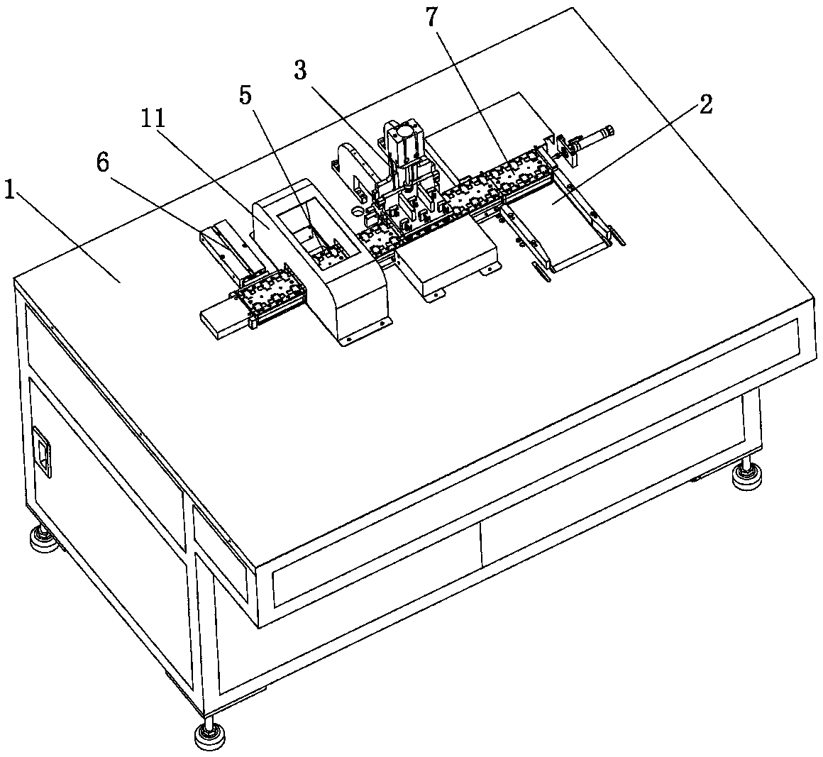
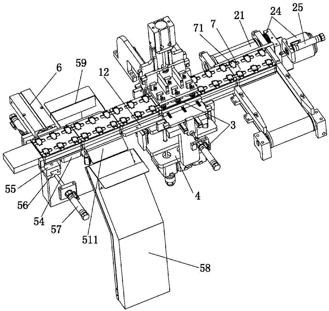
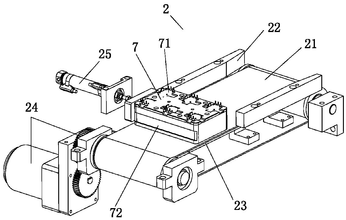
[0020] Refer to attached figure 1 to attach Image 6 The specific implementation manner of the present invention is introduced.

[0021] Such as Figure 1-6 As shown, a heavy torsion logic type encoder 71 detection machine includes a detection platform 1, a linear detection material path arranged on the detection platform 1, and a treatment machine equipped with six encoders 71 to be detected that travel along the linear detection material path. With 7, the detection table 1 is provided with a feeding device 2, a detection device 3, a rotary device 4 for rotating an encoder 71, a rotating shaft 711, and a screening device 5 for screening defective products along the straight line detection channel; the rotary device 4 is arranged on the detection device 3, the detection device 3 includes an upper detection component and a side detection component; the jig 7 is formed with a plurality of placement slots, and the bottom of the placement slots is provided with a through hole fo...


PUM


Abstract

The invention discloses a heavy torque logical encoder detection machine, which comprises a detection table, a linear detection material passage and a tooling, wherein the linear detection material passage is arranged on the detection table; the tooling advances along the linear detection material passage and carries a plurality of encoders to be detected; the detection table is sequentially provided with a feeding device, a detection device, a rotating device for rotating an encoder rotating shaft and a screening device for screening rejection products along the linear detection material passage; the rotating device is arranged right under the detection device; the detection device comprises an upper detection assembly and a side detection assembly; the tooling is provided with a plurality of placing grooves; a through hole through which the encoder to be detected passes is arranged at the groove bottom of the placing grooves. The heavy torque logical encoder detection machine has theadvantages that the structure is reasonable; through the duplex ascending and descending and a clamping tube, a clamp claw sleeves on the encoder rotating shaft; the rotating motor is enabled to stably drive the rotating shaft to rotate; the complete test of the work condition of the encoder is ensured. Through the driving assembly, the swinging seat swings towards the two sides; the fast screening on the encoder is realized; the test efficiency is improved.

Description

technical field [0001] The invention relates to the field of encoder detection equipment, in particular to a heavy torque logic type encoder detection machine. Background technique [0002] In the traditional encoder production process, after the encoder is assembled, it needs to be inspected to test the quality of the encoder and improve the yield rate of the shipment. If the static inspection can only detect the instantaneous signal of the encoder, it cannot be completely The entire working condition of the encoder is detected. If dynamic detection is used, the encoder shaft needs to be rotated to test the complete working condition of the encoder. However, in the existing testing machines, the rotating motor that drives the shaft of the encoder cannot be connected to the shaft quickly and stably, and the rotating motor cannot drive the shaft of the encoder well, especially for testing heavy-torque logic encoders, because The damping of the shaft rotation of the heavy tor...

Claims


Application Information

Patent Timeline
Patent Type & Authority Applications(China)
IPC IPC(8): B07C5/02B07C5/34B07C5/36
CPCB07C5/02B07C5/34B07C5/362
Inventor 曾河
Owner 广东钺河智能科技有限公司
Learn More