Automatic control technology complete set of plant of tap hole gate valve steel slag-blocking system

A complete set of equipment and tapping hole technology, which is applied in the manufacture of converters, etc., can solve the problems of accuracy and investment timing, unstable slag blocking effect, etc., and achieve the effects of automatic control, reasonable structure, and improved molten steel quality

Inactive Publication Date: 2010-06-09
福建三钢闽光股份有限公司 +1
View PDF6 Cites 0 Cited by
  • Summary
  • Abstract
  • Description
  • Claims
  • Application Information

AI Technical Summary

Problems solved by technology

[0004] Other slag blocking methods are put into operation at the end of tapping, and the accuracy and timing of the investment are difficult to grasp
At the same time, affected by the viscosity of the slag and the erosion of the tap hole, the slag blocking effect is unstable
[0005] We consider using translational slag blocking, but the structure of the gate valve must adapt to the high temperature environment. At the same time, the gate valve opening and closing actuator, and the supporting mechanism for the actuator must also adapt to the high temperature and rotating operating conditions of the converter. The slag rate is to improve the quality monitoring of molten steel. Automatic control is also a comprehensive supporting technology that must be considered.

Method used


Image

  • Automatic control technology complete set of plant of tap hole gate valve steel slag-blocking system
  • Automatic control technology complete set of plant of tap hole gate valve steel slag-blocking system
  • Automatic control technology complete set of plant of tap hole gate valve steel slag-blocking system

Examples


Embodiment Construction

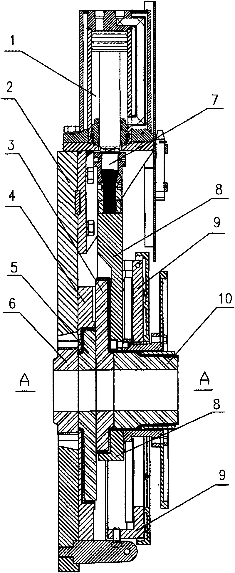
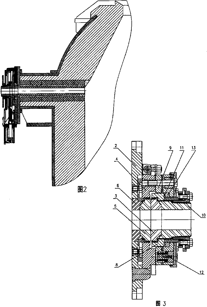
[0021] The gate valve slag retaining device includes a valve body and a valve core, and is characterized in that the valve body is composed of a connecting plate (2) part, a mounting plate (4) and a door frame (9). The inner nozzle brick (6) is fixed in the center of the connecting plate (2) ), the top of the connecting plate (2) is connected with the fixed mounting plate (4) by bolts; the central part of the mounting plate (4) is fixed with an inner slide brick (5), and the top of the mounting plate (4) is connected with the door frame (9) by a hinge pin; Door frame (9) center is fixed with outer nozzle brick (10), and door frame (9) both sides protrudes downwards and extends two rectangular slide rails, slide rail upper side is fixed with slide bar (13), on slide bar (13) A sliding frame (8) is installed in the space between the bottom and the upper surface of the mounting plate (4), the outer sliding brick (3) is installed in the center of the sliding frame (8), and the end ...


PUM


Abstract

The invention relates to an automatic control technique complete device for a tap hole gate valve slag stopping system, which relates to a steelmaking converter molten steel slag stopping system and comprises a gate valve slag stopping device, a water-cool oil cylinder and a five-way rigid spinning device. The gate valve slag stopping device is a translational valve gate, a sliding gate draws refractories and a valve core is started up / shut down; the water-cool oil cylinder is a hydraulic cylinder and positioned in a cool-water tank body; the five-way rigid spinning device is also arranged inthe cool-water tank body; a slag detection device is a CPU which is used for carrying out image processing over signals input by a far infrared heat inspection device, calculating real-time area energy ratio and comparing with a preset value, so that a comparative result controls the startup of the gate valve. The complete device has the advantages that: the translational valve gate has a reasonable structure; the valve gate adopts heat proof rolled steel and is suitable for high temperature operation together with refractories; the water-cool oil cylinder reduces the temperature of the oil cylinder and guarantees the working conditions of a sealing piece; the five-way rigid spinning device is communicated in a rigid manner and used for cooling an oil circuit simultaneously; the slag detection device adopts the signal image CUP to process and control the gate valve in real time to start up and shut down for slag stopping so as to improve the quality of molten steel; and the complete device fulfills automatic control.

Description

Technical field: [0001] The invention relates to a slag retaining mechanism for molten steel in a steelmaking converter. Background technique: [0002] In order to improve the slag blocking effect of the converter, in-depth research has been carried out on the slag blocking technology at home and abroad. Since Japan invented the slag-stopping ball slag-stopping tapping technology in 1970, various countries have invented dozens of slag-stopping methods to improve the converter tapping slag-stopping technology, and are still improving and perfecting continuously. Known slag blocking methods for converter tapping include the slag ball method, the slag plug method, the pneumatic slag blocking method, the slag blocking rod method, and the like. [0003] Pneumatic slag blocking is to use electronic slag indicator to monitor the steel flow, and according to the detection signal, a pneumatic device is used to push the refractory plug to block the steel outlet for slag blocking. Th...

Claims


Application Information

Patent Timeline
Patent Type & Authority Patents(China)
IPC IPC(8): C21C5/46
Inventor 赖兆奕任世美张桂林柯建祥陈伯瑜黄标彩罗源奎李金土赖浪泉
Owner 福建三钢闽光股份有限公司
Why Eureka
Try Eureka