
Water pipe automatic storage device

A technology for storage devices and water pipes, which is applied in the directions of transportation and packaging, delivery of filamentous materials, thin material processing, etc. It can solve the problems of cumbersomeness, low efficiency, and long time consumption, and achieve the effect of flexible and convenient operation and convenient rolling

Active Publication Date: 2018-09-11
SHANDONG INST OF POMOLOGY
View PDF7 Cites 7 Cited by
  • Summary
  • Abstract
  • Description
  • Claims
  • Application Information

AI Technical Summary

Problems solved by technology

[0002] Modern vegetable and fruit planting usually adopts the method of laying water pipes to automatically water large-scale vegetable and fruit gardens. However, there is no good collection method for water pipe collection. After laying water pipes, it is often necessary to manually roll up the water pipes. Extremely long, and the manual work is also very labor-intensive and inefficient
Especially for large orchards and planting bases, the water pipes are very large and cumbersome

Method used


Image

  • Water pipe automatic storage device
  • Water pipe automatic storage device
  • Water pipe automatic storage device

Examples


Embodiment 1

[0059] see Figure 1-7

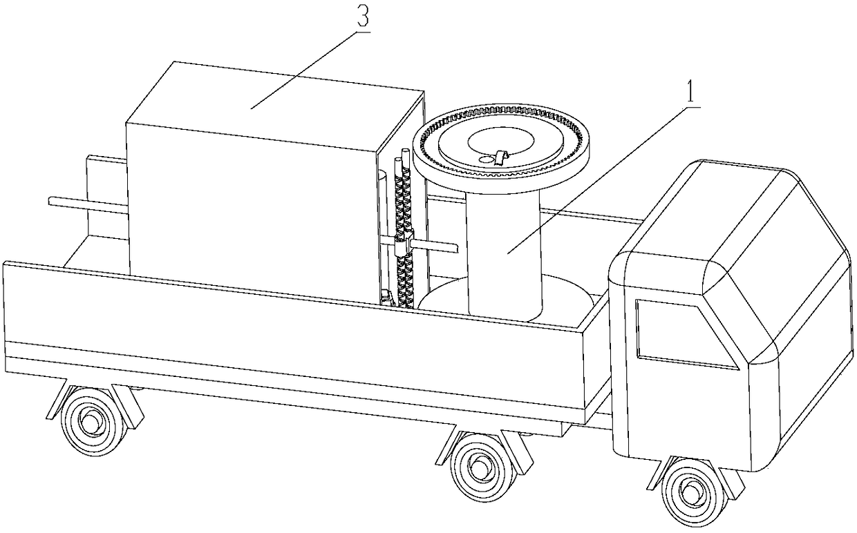
[0060] The invention provides an automatic storage device for water pipes, which includes a pipe collection mechanism arranged on the car body;

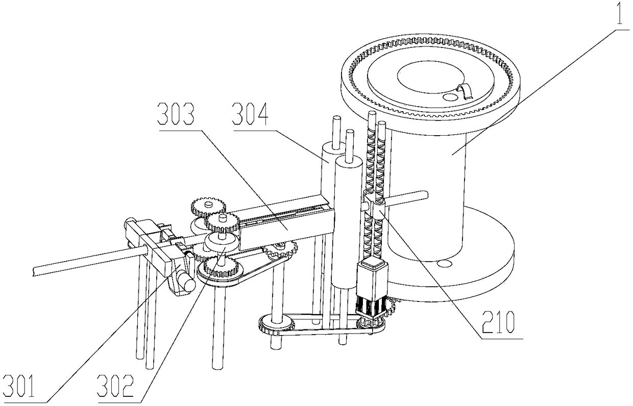
[0061] The tube receiving mechanism includes a tube winding mechanism for fixing and rotating the tube shaft 1, and a tube pulling mechanism 3 arranged on one side of the tube winding mechanism for pulling the water pipe;

[0062] The pipe winding mechanism includes a base, on which the pipe shaft 1 is plugged; the driving mechanism drives the pipe shaft 1 to rotate; the water pipe to be stored is fixed on the pipe shaft 1 after passing through the pipe pulling mechanism 3;

[0063] The tube pulling mechanism 3 includes an inlet and an outlet, and hot air blowers 301 are arranged on both sides of the inlet.

[0064] The drive mechanism uses the motor as the power source, and the gear combination as the power transmission mechanism. (not shown in the figure)

Embodiment 2

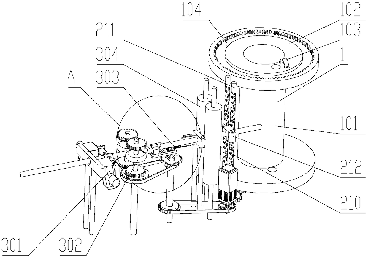
[0066] Others are the same as in Embodiment 1, except that the tube shaft 1 includes a shaft body 101 in the middle and baffles 102 provided at both ends of the shaft body 101; a through hole 4 is provided on the baffle plate 102 near the shaft body 101, and the through hole Four inner diameters are greater than the outer diameter of the water pipe, and the outside of the baffle plate 102 is provided with a semicircular hoop 103, the hoop 103 is arranged on one side of the through hole 4 on the baffle plate 102, one end of the hoop 103 is hinged with the baffle plate 102, and the other end It is locked and connected with the baffle plate 102 through a lock; the baffle plate 102 is a circular plate.

Embodiment 3

[0068] On the basis of Embodiment 2, an annular groove 104 is provided on the outer surface of the baffle plate 102, and a ring gear is arranged in the groove body of the annular groove 104. The ring gear meshes with the driving gear of the tube shaft 1, and the driving gear of the tube shaft 1 is driven by the driving mechanism.

[0069] The drive mechanism uses the motor as the power source, and the gear combination as the power transmission mechanism.


PUM


Abstract

The invention discloses a water pipe automatic storage device and relates to the field of agricultural equipment. According to the technical scheme, the water pipe automatic storage device comprises apipe storing mechanism arranged on a vehicle body; the pipe storing mechanism comprises a pipe winding mechanism and a pipe pulling mechanism arranged on one side of the pipe winding mechanism and used for pulling a water pipe; the pipe winding mechanism comprises a base and a pipe shaft, and the pipe shaft is inserted in the base; a driving mechanism is arranged at the end, close to the base, ofthe pipe shaft; and the pipe pulling mechanism comprises an inlet and an outlet, and air heaters are arranged on the two sides of the inlet. The water pipe automatic storage device has the beneficialeffects that by arranging the air heaters, softening of the water pipe in winter is facilitated, so that when the water pipe is subjected to winding storage, season crack of the wound water pipe dueto the fact the temperature is excessively low and consequently the water pipe is hardened is reduced; unique extrusion discs serve as the pulling device of the water pipe, thus pulling of the water pipe with elasticity is ensured, and the water pipe is further not liable to be damaged; and sundried on a water pipe body can be effectively cleared away by a cleaning cylinder, and then through rotating of the pipe shaft and up-down moving of a pipe arranging device on two-way lead screws, the purpose of automatically storing the water pipe is achieved.

Description

technical field [0001] The invention relates to the field of agricultural equipment, in particular to an automatic storage device for water pipes. Background technique [0002] Modern vegetable and fruit planting usually adopts the method of laying water pipes to automatically water large-scale vegetable and fruit gardens. However, there is no good collection method for water pipe collection. After laying water pipes, it is often necessary to manually roll up the water pipes. Extremely long, and the manual work labor load is also very big, inefficiency. Especially for large orchards and planting bases, the water pipes are very large and cumbersome. Contents of the invention [0003] In order to achieve the purpose of the above invention and address the above technical problems, the present invention provides an automatic storage device and method for water pipes. [0004] The technical solution is an automatic storage device for water pipes, including a collection mechan...

Claims


Application Information

Patent Timeline
IPC IPC(8): B65H54/44B65H54/70B65H54/28B65H67/04
CPCB65H54/2818B65H54/44B65H54/70B65H54/702B65H67/0411B65H2701/33
Inventor 韩真李勃李秀杰崔冬冬张庆田王晓芳刘利李晨
Owner SHANDONG INST OF POMOLOGY
Learn More