A high heat dissipation garden lamp structure

A technology of garden lights and high heat dissipation, which is applied in gardening, lighting and heating equipment, and components of lighting devices, etc. It can solve the problems of unsatisfactory heat dissipation performance of garden lights, increase the cost of garden maintenance facilities, and fail to meet the needs of garden use. Achieve the effects of improving water flow utilization, lowering temperature, and multiple functions

Active Publication Date: 2020-02-07
湖州众创小微创业园企业管理股份有限公司
View PDF4 Cites 0 Cited by
  • Summary
  • Abstract
  • Description
  • Claims
  • Application Information

AI Technical Summary

Problems solved by technology

In the garden, the garden lights can embellish the city scenery, illuminate the garden, decorate the garden, and improve people's interest in visiting the garden. The construction of the garden light is a conventional infrastructure construction. The existing garden lights only have the function of lighting, and the function is single. It cannot meet the needs of garden use. The garden also needs to maintain the garden plants, such as frequent watering, insect removal, fertilization, etc. In the existing gardens, sprinkler equipment is usually installed separately, which not only occupies too much garden space, but also increases the cost of the garden. The cost of maintenance facilities. In addition, garden lights will generate a lot of heat after long-term use. The heat dissipation performance of some garden lights is not ideal. When the heat cannot be dissipated in time, it is easy to cause damage to the garden light circuit.
Therefore, the existing garden lights have the problems of single function and unsatisfactory heat dissipation performance.

Method used


Image

  • A high heat dissipation garden lamp structure
  • A high heat dissipation garden lamp structure

Examples


Embodiment Construction

[0017] The present invention will be further described below in conjunction with the accompanying drawings and embodiments, but not as a basis for limiting the present invention.

[0018] Example.

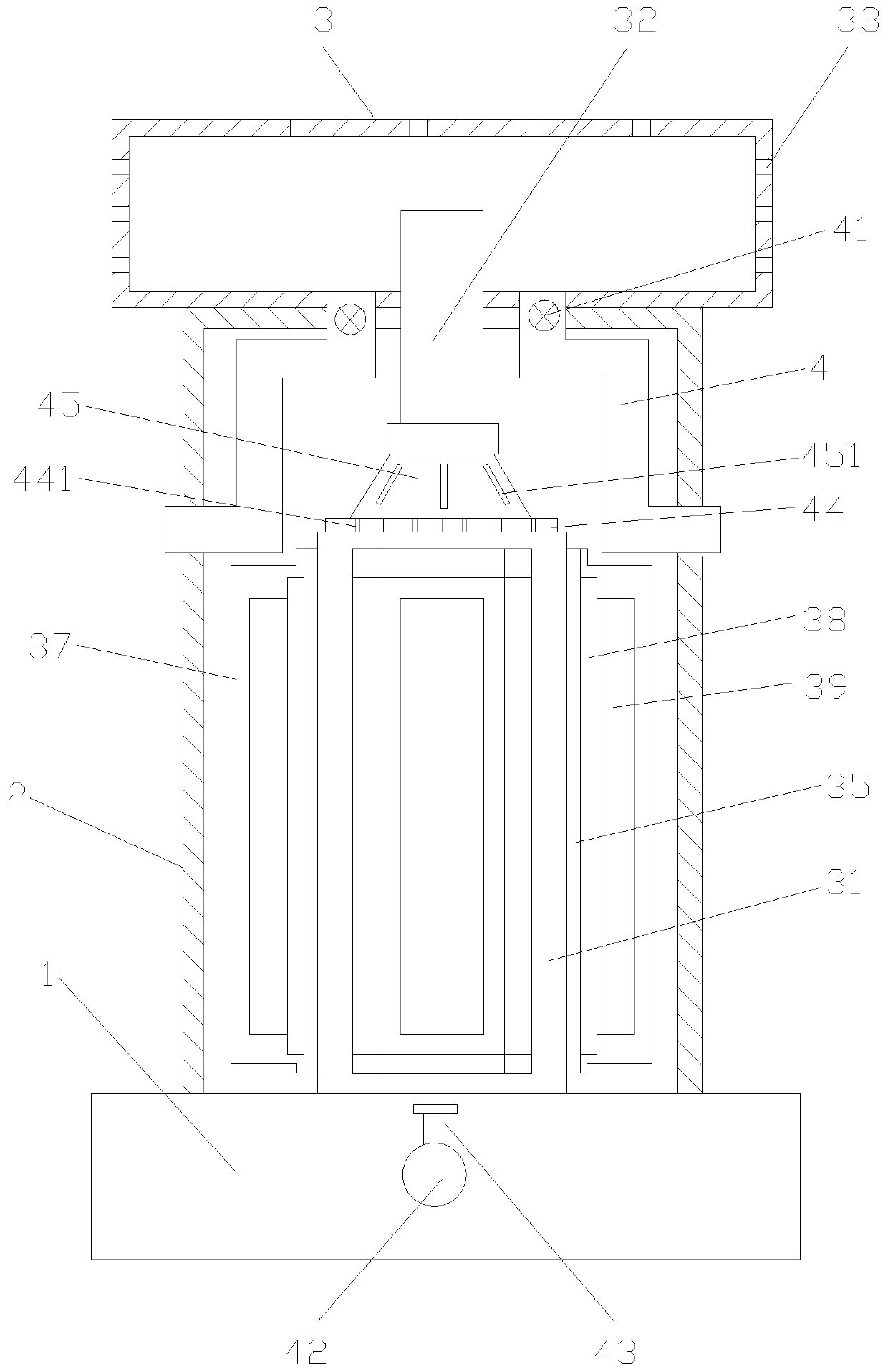
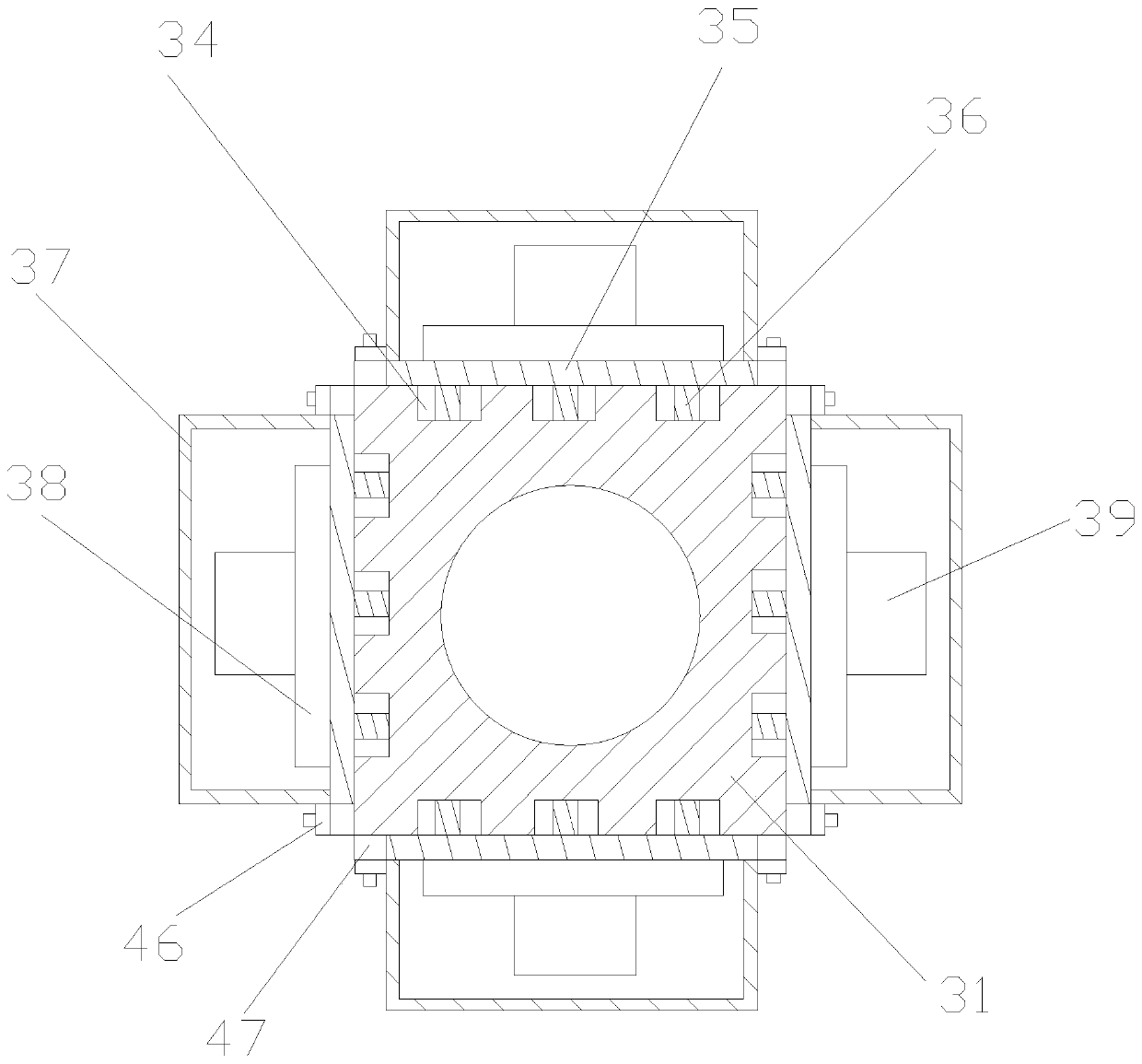
[0019] Such as figure 1 , figure 2 As shown, a high heat dissipation garden lamp structure includes a lamp holder 1, a lamp post 2 is provided above the lamp holder 1, a sprinkler 3 is provided above the lamp post 2, and the lamp post 2 Inside is provided with a water tank 31, the upper end of the water tank 31 is provided with a water spray pipe 32, one end of the water spray pipe 32 communicates with the water tank 31, and the other end of the water spray pipe 32 extends upwards into the water sprayer 3, the water spray The top surface and the side of device 3 are all provided with some spray holes 33; All sides of described water tank 31 are provided with heat conduction plate 35, and the side wall of described water tank 31 is provided with some grooves 34, and described hea...


PUM


Abstract

The invention discloses a high-heat-dissipation garden lamp structure. The high-heat-dissipation garden lamp structure comprises a lamp holder, wherein a lamp post is arranged above the lamp holder, awater sprayer is arranged above the lamp post, a water tank is arranged in the lamp post, a water spray pipe is arranged at the upper end of the water tank, one end of the water spray pipe is communicated with the water tank, the other end of the water spray pipe extends upwards into the water sprayer, and a plurality of water spray holes are formed in the top surface and the side surface of thewater sprayer separately; and a heat-conducting plate is arranged on each side surface of the water tank, a plurality of grooves are formed in the sidewall of the water tank, a plurality of heat-conducting columns stretching into the grooves are arranged at the inner side of the heat-conducting plate, heat dissipation silica gel is filled between the heat-conducting columns and the grooves, a circuit board is arranged at the outer side of the heat-conducting plate, an LED lamp is arranged on the surface of the circuit board, and a protection cover covering the circuit board and the LED lamp isfurther arranged on the heat-conducting plate. The high-heat-dissipation garden lamp structure disclosed by the invention has the characteristics of being diversified in function, and capable of effectively improving the heat dissipation performance.

Description

technical field [0001] The invention relates to a garden lamp, in particular to a garden lamp structure with high heat dissipation. Background technique [0002] Infrastructure refers to the physical and engineering facilities that provide public services for social production and residents' lives, and is a public service system used to ensure the normal progress of social and economic activities in a country or region. It is the general material condition for the survival and development of society. Infrastructure includes transportation, post and telecommunications, water supply and power supply, commercial services, scientific research and technical services, landscaping, environmental protection, cultural education, health services and other municipal public engineering facilities and public life service facilities. In the garden, the garden lights can embellish the city scenery, illuminate the garden, decorate the garden, and improve people's interest in visiting the g...

Claims


Application Information

Patent Timeline
Patent Type & Authority Patents(China)
IPC IPC(8): F21S8/00F21V29/71F21V29/74F21V33/00A01G25/02F21Y115/10F21W131/109
CPCA01G25/02F21S8/00F21V29/71F21V29/74F21V33/006F21W2131/109F21Y2115/10
Inventor 陆明芳
Owner 湖州众创小微创业园企业管理股份有限公司
Why Eureka
Try Eureka