Method and system for predicting temperature and humidity environment of machine room

A computer room temperature and humidity prediction method technology, applied in heating and ventilation control system, heating and ventilation safety system, control input involving environmental factors, etc., can solve labor cost and time cost, computer room temperature prediction, many parameters, etc. problems, to achieve the effect of improving energy efficiency and reducing the incidence of accidents

Inactive Publication Date: 2018-09-11
WUHAN WULIANYUAN TECH CO LTD +2
View PDF7 Cites 25 Cited by
  • Summary
  • Abstract
  • Description
  • Claims
  • Application Information

AI Technical Summary

Problems solved by technology

However, this method requires many parameters, and the labor cost and time cost are also relatively large, and this method does not consider the current environmental temperature and humidity, but only makes predictions based on several relatively fixed parameters, and cannot realize the temperature and humidity of the computer room. real-time prediction, there are certain defects
[0006] In summary, the existing computer

Method used


Image

  • Method and system for predicting temperature and humidity environment of machine room
  • Method and system for predicting temperature and humidity environment of machine room

Examples


Embodiment Construction

[0039] The specific implementation manners of the present invention will be further described in detail below in conjunction with the accompanying drawings and embodiments. The following examples are used to illustrate the present invention, but are not intended to limit the scope of the present invention.

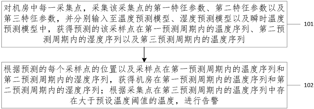
[0040] see figure 1 , is a schematic flowchart of a method for predicting the temperature and humidity environment of a computer room provided by an embodiment of the present invention. As shown in the figure, the method includes:

[0041] 101. For each collection point in the computer room, collect the first characteristic parameter, the second characteristic parameter, and the third characteristic parameter of the collection point, and input them into the temperature prediction model, humidity prediction model, and instantaneous temperature prediction model respectively to obtain the prediction The temperature series of the sampling point in the first forecast period, t...


PUM


Abstract

The invention provides a method and system for predicting the temperature and humidity environment of a machine room. The method comprises the steps that as for each sampling point in the machine room, a first characteristic parameter, a second characteristic parameter and a third characteristic parameter of the sampling point are collected, the first characteristic parameter is into a temperaturepredicting model to obtain the predicted temperature sequence of the sampling point in the first prediction period, the second characteristic parameter is input into a humidity predicting model to obtain the predicted humidity sequence of the sampling point in the second prediction period, and the third characteristic parameter is input into a transient temperature predicting model to obtain thepredicted temperature sequence of the sampling point in the third prediction period; the temperature sequence of the machine room in the first prediction period and the humidity sequence of the machine room in the second prediction period are obtained according to the predicted position of each sampling point and the temperature sequence of the sampling point in the first prediction period and thehumidity sequence of the sampling point in the second prediction period; and an alarm is given when temperature greater than the preset temperature threshold exists in the temperature sequence of each sampling point in the third prediction period. By means of the method and system for predicting the temperature and humidity environment of the machine room, energy consumption of the machine room is reduced, the energy utilization efficiency is improved, and the accident occurrence rate of the machine room is reduced.

Description

technical field [0001] The present invention relates to the technical field of computer room monitoring, and more specifically, to a method and system for predicting the temperature and humidity environment of a computer room. Background technique [0002] With the rapid development of information technology, the informatization level of all walks of life is constantly improving, and the informatization construction is also constantly strengthening. The computer room is a place for centralized storage of information equipment, which is crucial to the construction of information technology. The security of the computer room is the basis for the safe and reliable operation of the entire information system. As an essential part of the computer room, the computer room monitoring system can effectively monitor the environment and equipment working conditions of the computer room, and ensure the safe, stable, reliable and efficient operation of the computer room. [0003] Most of...

Claims


Application Information

Patent Timeline
IPC IPC(8): F24F11/61F24F11/88F24F110/10F24F110/12F24F110/20F24F130/10F24F140/50
CPCF24F11/61F24F11/88F24F2110/10F24F2110/12F24F2110/20F24F2130/10F24F2140/50
Inventor 刘志嘉许文俊刘汉锋黄春雷邓昶尹书霞
Owner WUHAN WULIANYUAN TECH CO LTD
Why Eureka
Try Eureka