
Focusing method and device for video surveillance

A technology of video monitoring and focusing method, which is applied in the direction of focusing device, color TV parts, TV system parts, etc. It can solve the problems of difficult focusing of point light sources, low production efficiency, and complicated process, so as to improve the focusing effect, The effect of improving production efficiency and simplifying the production process

Active Publication Date: 2020-09-04
深圳市瀚晖威视科技有限公司
View PDF4 Cites 0 Cited by
  • Summary
  • Abstract
  • Description
  • Claims
  • Application Information

AI Technical Summary

Problems solved by technology

[0002] In the field of video surveillance, in order to ensure that the image is always clear in changing surveillance scenes, it is usually necessary to focus according to changes in the actual surveillance scene. The focusing method is usually manual focusing, that is, the definition of video surveillance images is adjusted manually. , when there is a mechanical gear error, it will affect the focus. By manually matching different mechanical back focus and eliminating the mechanical error caused by the gear gap in the mechanical structure, it is guaranteed that the whole process is clear during the zooming process. In addition, manual focus When , there is a problem that the point light source is difficult to focus
It can be seen that the mechanical back focus adjustment process of conventional zoom module production is relatively complicated, which not only lowers production efficiency, but also causes waste of manpower

Method used


Image

  • Focusing method and device for video surveillance
  • Focusing method and device for video surveillance

Examples


Embodiment Construction

[0020] The following will clearly and completely describe the technical solutions in the embodiments of the present invention with reference to the accompanying drawings in the embodiments of the present invention. Obviously, the described embodiments are only some, not all, embodiments of the present invention. Based on the embodiments of the present invention, all other embodiments obtained by persons of ordinary skill in the art without making creative efforts belong to the protection scope of the present invention.

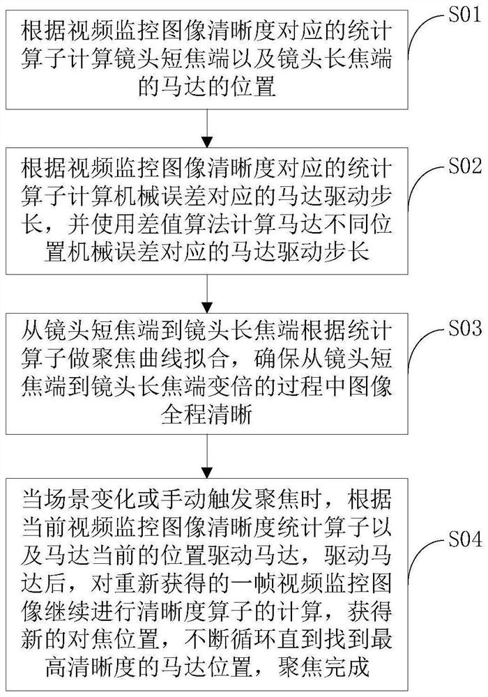
[0021] In the video monitoring focusing method and device embodiment of the present invention, the flow chart of the video monitoring focusing method is as follows figure 1 shown. figure 1 Among them, the focusing method of the video surveillance includes the following steps:

[0022] Step S01 calculates the position of the motor at the short-focus end of the lens and the motor at the long-focus end of the lens according to the statistical calculation corresp...


PUM


Abstract

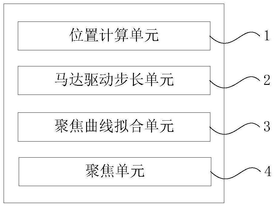
The invention discloses a focusing method and device for video monitoring. The method includes: calculating the positions of the short-focus end of the lens and the motor position of the long-focus end of the lens according to a statistical calculator corresponding to the definition of the video monitoring image; The statistical calculator calculates the motor drive step length corresponding to the mechanical error, and calculates the motor drive step length corresponding to the mechanical error at different positions of the motor; from the short-focus end of the lens to the long-focus end of the lens, the focus curve is fitted according to the statistical calculator; when the scene changes Or when the focus is manually triggered, the motor is driven according to the current video surveillance image definition statistics calculator and the current position of the motor, and the calculation of the definition operator is continued on the regained frame of video surveillance image to obtain a new focus position, and the cycle continues Until the motor position with the highest definition is found, the focus is completed. The invention can simplify the production process, improve the production efficiency, change the focus of video monitoring from manual to automatic, save manpower, and improve the focusing effect of point light sources.

Description

technical field [0001] The invention relates to the field of video monitoring, in particular to a focusing method and device for video monitoring. Background technique [0002] In the field of video surveillance, in order to ensure that the image is always clear in changing surveillance scenes, it is usually necessary to focus according to changes in the actual surveillance scene. The focusing method is usually manual focusing, that is, the definition of video surveillance images is adjusted manually. , when there is a mechanical gear error, it will affect the focus. By manually matching different mechanical back focus and eliminating the mechanical error caused by the gear gap in the mechanical structure, it is guaranteed that the whole process is clear during the zooming process. In addition, manual focus When , there is a problem that the point light source is difficult to focus. It can be seen that the mechanical back focus adjustment process of conventional zoom module...

Claims


Application Information

Patent Timeline
Patent Type & Authority Patents(China)
IPC IPC(8): H04N5/232G03B13/36H04N7/18
CPCH04N7/18G03B13/36H04N23/67
Inventor 裴瑞宏韩畅花涛刘彬
Owner 深圳市瀚晖威视科技有限公司
Learn More