Material analysis and detection method based on image recognition technology

An image recognition and detection method technology, applied in the field of material analysis and detection based on image recognition technology, can solve the problems of slow growth cycle of employees' skill level, inability to ensure misjudgment by observers, mixed parts and material grades, etc. The effect of high accuracy and rapid cultivation

Pending Publication Date: 2022-04-01
CHENGDU AIRCRAFT INDUSTRY GROUP +1
View PDF0 Cites 0 Cited by
  • Summary
  • Abstract
  • Description
  • Claims
  • Application Information

AI Technical Summary

Problems solved by technology

Therefore, the above-mentioned prior art mainly has the following disadvantages: (1) long-term spectral observation may cause excessive eye use, which may damage the eyesight of employees; (2) require high professional skills for employees, Relevant professional training is required, and the growth cycle of employee skills is extremely slow; (3) the eyepiece can only be observed by a single person, and it is impossible to ensure that the observer does not make a misjudgment; (4) there are many aviation parts, and the material grades of the front and rear parts will be mixed. And parts wrong detection, missing detection and other problems

Method used


Image

  • Material analysis and detection method based on image recognition technology
  • Material analysis and detection method based on image recognition technology
  • Material analysis and detection method based on image recognition technology

Examples


Embodiment 1

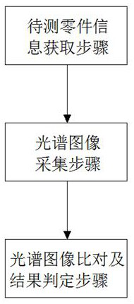
[0045] This embodiment discloses a material analysis and detection method based on image recognition technology, which specifically includes the following steps:

[0046] Steps for obtaining the information of the parts to be tested: Before testing, first use the label recognizer to scan the identification label of the part to be tested to obtain the detection quantity of the part to be tested and the brand name of the part, and then the label recognizer transmits the above part information to the host computer , the host computer searches and matches in the stored database according to the above part information, and finally determines the standard spectrum for comparison;

[0047] Spectral image acquisition steps: put the part to be tested on the detection platform of the spectrum mirror, turn on the switch, the host computer first stimulates the spectrum mirror to generate sparks, then controls the rotation of the servo motor, and the servo motor drives the knob of the spect...

Embodiment 2

[0050]This embodiment discloses a material analysis and detection method based on image recognition technology. On the basis of Embodiment 1, this embodiment makes further limitations and explanations for the analysis and detection method. In this embodiment, In the spectral image collection step, the splicing of multiple spectral images collected in order using the coordinate system specifically refers to splicing the rightmost edge of the first picture with the left edge of the second picture, and the new The height of the picture is the same as the original two Figure 1 Coherent, and the width is the sum of the two pictures.

[0051] Further, the spectral image comparison and result determination step specifically includes the following steps:

[0052] Image digitization steps: first convert the RGB color value of each pixel on the inspection spectrum image of the part to be tested into the gray value of the pixel through the following calculation expression

[0053] S=1...

Embodiment 3

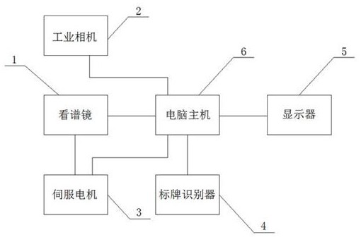
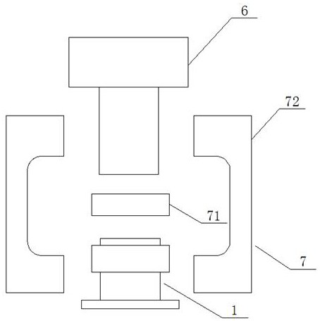
[0082] This embodiment discloses a material analysis and detection device based on image recognition technology. figure 2 , mainly including spectroscope 1, industrial camera 2, servo motor 3, signage recognizer 4, display 5 and computer host 6, said computer host 6 is connected with spectroscope 1, industrial camera 2, servo motor 3, signage recognition respectively Device 4 and display 5 are connected, and it is the control terminal of the whole device. The spectrum mirror 1 is a prior art, and it is a finished product on the market. The industrial camera 2 is arranged on the spectrum mirror 1 through the camera mount 7. On the eyepiece, the output end of the servo motor 3 is connected with the knob on the spectroscope 1, and the label identifier 4 is an RFID reader.

[0083] Further, refer to the attached figure 2 , the camera mount 7 includes a lens adapter ring 71 and a camera bracket 72, one end of the lens adapter ring 71 is connected with the lens of the industrial ...


PUM


Abstract

The invention relates to the technical field of material analysis, and discloses a material analysis and detection method based on an image recognition technology, which mainly comprises a to-be-detected part information acquisition step, a spectral image acquisition step and a spectral image comparison and result judgment step. Compared with an existing manual mode for analyzing the spectrum of the part material, the method has the advantages that the growth difficulty and period of professional skill talents are reduced, the whole analysis process does not depend on the professional skill level of detection personnel any more, the accuracy of the analysis result is higher, and the accuracy of the analysis result is improved through automatic acquisition and analysis of the spectrum image. And the labor intensity of detection personnel is also reduced.

Description

technical field [0001] The present application relates to the technical field of material analysis, in particular to a material analysis and detection method based on image recognition technology. Background technique [0002] Spectrum analysis technology is a kind of spontaneous transition from high-energy state to low-energy state according to each element atom or ion. According to its spectrum diagram, it can be found visually, and there will be a corresponding spectral line with a certain wavelength. Among the many spectral lines emitted by the atoms or ions of each element, there are always some spectral lines with special wavelength (color) and intensity (brightness), which form the characteristic spectral lines of the element. On the contrary, each spectral line in the spectrogram must correspond to a spontaneous transition of an atom or ion of a certain element. Therefore, according to the presence or absence of characteristic spectral lines of atoms or ions of an e...

Claims


Application Information

Patent Timeline
Patent Type & Authority Applications(China)
IPC IPC(8): G06T7/00G06T7/90G01N21/31
Inventor 虞永杰杨扬王邦凯尹松松范玲玲王小兵
Owner CHENGDU AIRCRAFT INDUSTRY GROUP
Why Eureka
Try Eureka