Check patentability & draft patents in minutes with Patsnap Eureka AI!

Backmixing preventing system

An anti-return and ash hopper technology, which is applied in the direction of the swirl axis can be reversed, the swirl device, etc., to achieve the effect of improving the discharge quality and reducing the escape.

Active Publication Date: 2018-09-14
HUANGSHI SUNNY SCI & TECH CO LTD
View PDF6 Cites 1 Cited by
  • Summary
  • Abstract
  • Description
  • Claims
  • Application Information

AI Technical Summary

Problems solved by technology

[0004] The purpose of the present invention is to address the above problems, to provide an anti-return mixing system, which is applied inside the ash hopper, reduces the escape of dust entering the ash hopper, and can realize the anti-cyclone dust collector at the cost of lower energy consumption. The secondary purification of the exhaust airflow improves its emission quality and improves the above problems

Method used


Image

  • Backmixing preventing system
  • Backmixing preventing system
  • Backmixing preventing system

Examples


no. 1 example

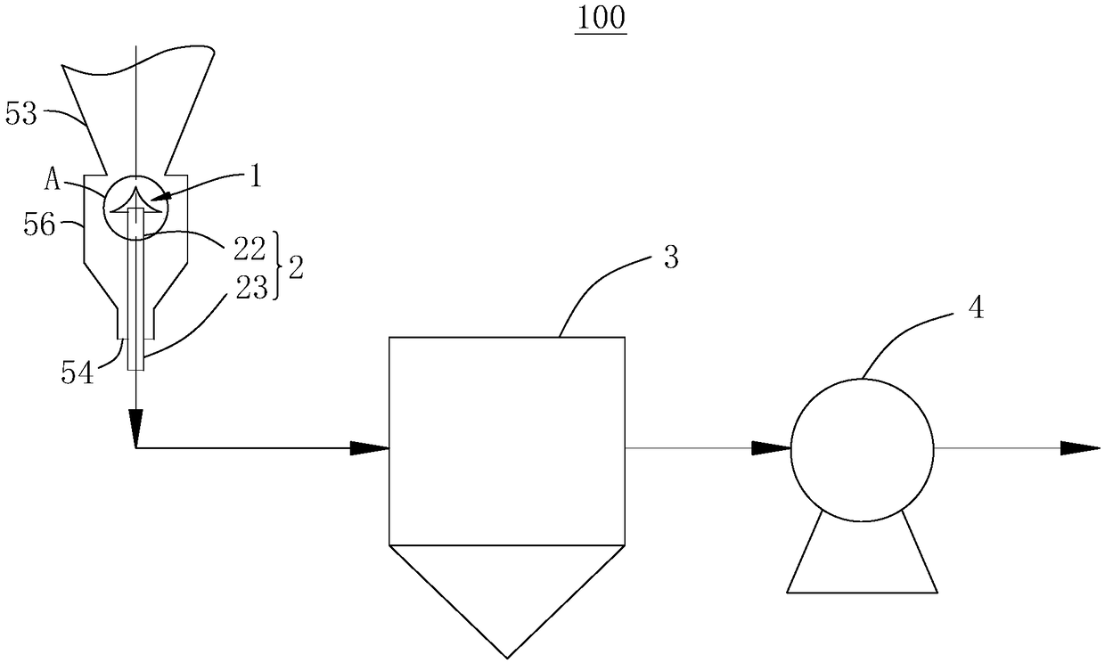
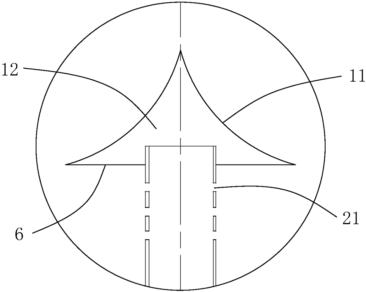
[0032] Please refer to figure 2 This embodiment provides an anti-backmixing system 100, which is applied in the ash hopper 56 of a cyclone dust collector, and includes an anti-backmixing cone 1 and an air extraction mechanism.

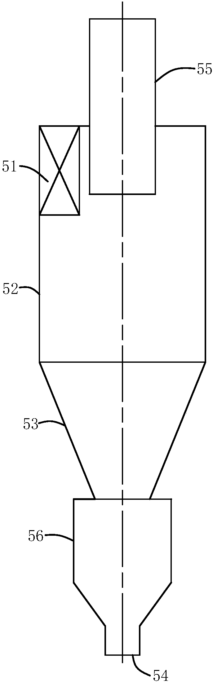
[0033] Such as figure 1 As shown, according to the structure of the cyclone dust collector, the dust collector separation section includes a separation cylinder section 52 and a separation cone section 53, the separation cylinder section 52 is connected to the separation cone section 53, and the dust-containing gas inlet 51 of the cyclone dust collector is located in the separation cylinder In section 52, the bottom of the separating cone section 53 is connected to the ash hopper 56. The separated high-concentration dust-containing gas enters the ash hopper 56 through the inlet of the ash hopper 56; the purified gas is discharged from the gas riser 55. In this embodiment, the anti-backmixing system 100 is adopted on the existing cyclone dust collector, th...

no. 2 example

[0050] Researchers have studied the anti-backmixing system 100 provided by the present invention, based on the above-mentioned first embodiment, can also make the following optional other structural solutions, which are specifically described as follows:

[0051] Such as Figure 5 As shown, in this embodiment, the fixing assembly 6 includes a disc 62, the disc 62 is connected to the bottom of the concave circular arc conical surface 11, the disc 62 closes the open end of the containing cavity 12, and the suction pipe 2 passes through the disc 62 Extending into the accommodating cavity 12, the disc 62 is provided with a plurality of vent holes 63, the vent holes 63 are arranged around the circumference of the disc 62, the vent holes 63 penetrate the disc 62, so that the cavity in the ash hopper 56 and the accommodating cavity 12 is connected, and the dust-containing gas enters the containing cavity 12 through the vent 63 under the action of the suction assembly 4, and then enters ...


PUM


Abstract

The invention relates to a backmixing preventing system, and belongs to the technical field of gas-solid separation. The backmixing preventing system is applied to a dust hopper of a cyclone dust collector and comprises a backmixing preventing cone and a gas pumping mechanism; the backmixing preventing cone is located in the dust hopper, the backmixing preventing cone is close to a dust inlet of the dust hopper, and the gas pumping mechanism comprises a gas pumping pipe, a purifying assembly and a gas pumping assembly; one end of the gas pumping pipe is connected with the backmixing preventingcone, and the other end of the gas pumping pipe is located outside the dust hopper and connected with the purifying assembly; and dust-containing gas in the dust hopper can be pumped into the purifying assembly under the effect of the gas pumping assembly, and the dust-containing gas is exhausted through the gas pumping assembly after being purified through the purifying assembly. The backmixingpreventing system is applied into the dust hopper, escaping of fine dust entering the dust hopper is reduced, secondary purification of a gas flow exhausted from the cyclone dust collector is achievedunder the price of low energy consumption, and the separation efficiency of the cyclone dust collector is improved.

Description

Technical field [0001] The invention relates to the technical field of gas-solid separation, in particular to an anti-backmixing system. Background technique [0002] The principle mechanism of cyclone dust collector is as follows figure 1 As shown, the dust-containing airflow enters the cyclone dust collector from the dust-containing gas inlet 51 of the cyclone dust collector, and spiral flows are generated in the separation cylinder section 52 and the separation cone section 53, and the spiral flow is of any cross section in the separation cylinder section 52 and the separation cone section 53. The flow is divided into two areas, the outer swirling flow and the inner swirling flow. The part close to the inner wall of the cylinder is the outer swirling flow, and the spiral direction of the gas flows downward; the area near the center (including the center point) is the inner swirling flow. The spiral direction of the gas flows upward. The downward swirling flow will generate ce...

Claims


Application Information

Patent Timeline
Patent Type & Authority Applications(China)
IPC IPC(8): B04C5/185B04C9/00B04C11/00
CPCB04C5/185B04C9/00B04C11/00
Inventor 刘根凡龙薪羽蒋胜杨建军陈洲
Owner HUANGSHI SUNNY SCI & TECH CO LTD
Features
  • R&D
  • Intellectual Property
  • Life Sciences
  • Materials
  • Tech Scout
  • Unparalleled Data Quality
  • Higher Quality Content
  • 60% Fewer Hallucinations
Learn More