Clutch shifting fork punching equipment

A technology of clutch shift fork and stamping equipment, which is applied in the field of mechanical processing, can solve the problems that affect the precision of stamping and the easy displacement of metal plates, etc., and achieve the effects of ensuring accuracy, avoiding warping, and ensuring consistency

Active Publication Date: 2018-09-14
重庆驰明汽车配件有限公司
View PDF8 Cites 3 Cited by
  • Summary
  • Abstract
  • Description
  • Claims
  • Application Information

AI Technical Summary

Problems solved by technology

[0004] The present invention intends to provide a clutch shift fork punching equipment to solve the problem that the metal plate is prone to displacement during the punching process and affects the punching accuracy

Method used


Image

  • Clutch shifting fork punching equipment

Examples


Embodiment Construction

[0017] The present invention will be described in further detail below by means of specific embodiments:

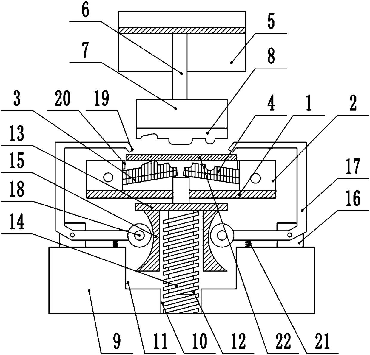
[0018] The reference signs in the drawings of the description include: stamping base 1, fixed block 2, stamping backing plate 3, die 4, cylinder body 5, piston rod 6, pressing module 7, punch 8, support table 9, the first A groove 10, a second groove 11, a support column 12, a fixed plate 13, a support spring 14, a U-shaped block 15, a bump 16, a jaw 17, a roller 18, a pressing block 19, a limit block 20, a telescopic Spring 21, metal plate 22.

[0019] The embodiment is basically as figure 1 Shown: a clutch shift fork stamping equipment, including a stamping base 1, two fixed blocks 2 are fixedly connected to the stamping base 1, the fixed blocks 2 are provided with a limit block 20, and the fixed block 2 Both are rotatably connected with a stamping backing plate 3, and the bottom of the stamping backing plate 3 is provided with a rubber pad. Stamping mechanism, the s...


PUM


Abstract

The invention relates to clutch shifting fork punching equipment which comprises a punching base; fixed blocks are arranged on the punching base; two punching cushion plates are rotationally connectedto the fixed blocks respectively and can abut against each other; a cylinder body and a piston rod are arranged above the punching cushion plates; a lower pressure module is fixedly connected to thebottom end of the piston rod; a supporting table is arranged below the punching base and is provided with a first groove; the first groove is internally provided with a supporting column; the top endof the supporting column penetrates through the punching base and abuts against the punching cushion plates; the supporting column is transversely provided with a fixed plate in a sleeving manner; a supporting spring sleeves the external of the supporting column below the fixed plate; the other end of the supporting spring is fixedly connected to the bottom of the first groove; U-shaped blocks arefixedly connected to the two sides of the fixed plate respectively; lugs are arranged at the two ends of the supporting table respectively; a clamping jaw is rotationally connected to each lug; a rolling wheel is rotationally connected to one end of each clamping jaw and abuts against each U-shaped block; the other end of each clamping jaw is provided with an abutting block which is bended downward. The device can perform clamping work in the punching process.

Description

technical field [0001] The invention relates to the field of mechanical processing, in particular to a stamping equipment for a clutch shift fork. Background technique [0002] The clutch is installed between the engine and the transmission, and is an assembly directly connected with the engine in the car drive train. Usually, the clutch is installed together with the flywheel set of the engine crankshaft, which is the part that cuts off and transmits power between the engine and the vehicle transmission system. During the whole process of the car from starting to normal driving, the driver can manipulate the clutch as needed to temporarily separate or gradually engage the engine and drive train to cut off or transfer the power output from the engine to the drive train. Its function is to make the engine and the transmission gradually engage, so as to ensure the smooth start of the car; temporarily cut off the connection between the engine and the transmission, so as to fac...

Claims


Application Information

Patent Timeline
Patent Type & Authority Applications(China)
IPC IPC(8): B21D22/02B21D37/10B21D43/00B21D43/22B21D37/04B21D53/84
Inventor 黎志
Owner 重庆驰明汽车配件有限公司
Why Eureka
Try Eureka