
Injection moulding equipment

A technology of injection molding and equipment, applied in the direction of electrical components, electrical switches, circuits, etc., can solve problems such as waste, hidden safety hazards, and electricity consumption, and achieve the effect of convenient operation and simple structure

Inactive Publication Date: 2018-09-14
广州市灵汐科技有限公司
View PDF0 Cites 0 Cited by
  • Summary
  • Abstract
  • Description
  • Claims
  • Application Information

AI Technical Summary

Problems solved by technology

Injection molding is realized through injection molding machines and molds. However, usually the staff will often forget to turn off the power after using it. The injection molding machine is easy to cause electricity consumption when it is not in use. There are a lot of problems. Necessary waste, but also a great potential safety hazard

Method used


Image

  • Injection moulding equipment
  • Injection moulding equipment
  • Injection moulding equipment

Examples


Embodiment Construction

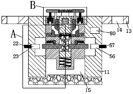
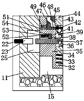
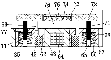
[0014] Such as Figure 1-Figure 5As shown, an injection molding equipment of the present invention includes a base 11, a power feeding device arranged in the base 11 and a locking device arranged in the base 11, and the power feeding device includes a set Up and down through the loading cavity 15 arranged in the base 11, the left and right of the loading cavity 15 are symmetrically provided with a countersunk 25 located in the loading cavity 15 and communicating with the loading cavity 15, and the sinking on the left side A first power feeding block 23 is fixedly arranged on the left inner wall of the mouth 25, and the left end of the first power feeding block 23 is fixedly connected to a power supply located in the base 11 and has one end extending out of the left end surface of the base 11. The outer first wire 22, the second power feeding block 56 is fixedly installed in the right inner wall of the right side of the counterbore 25, and the right end of the second power feed...


PUM


Abstract

The present invention discloses injection moulding equipment, which includes a base, an electricity feeding device arranged in the base and an interlocking device arranged in the base. The electricityfeeding device includes a loading chamber running through the base up and down, sink ports located in the loading chamber and communicated with the loading chamber are disposed on the left and rightof the loading chamber symmetrically, a first electricity feeding block is fixedly disposed on the left inner wall of the left sink port, the left end of the first electricity feeding block is fixedlyconnected to a first lead that is located in the base and has one end extending out of the left end face of the base, a second electricity feeding block is fixedly disposed on the right inner wall ofthe right sink port, and the right end of the second electricity feeding block is fixedly connected to a second lead that is located in the base and has one end extending out of the right end face ofthe base.

Description

technical field [0001] The invention relates to the technical field of injection molding, in particular to injection molding equipment. Background technique [0002] At present, many enterprises will use injection molding machines. Injection molding machines are a kind of plastic machinery, referred to as injection machines or injection molding machines. They are the main molding equipment for making thermoplastic or thermosetting plastics into various shapes of plastic products using plastic molding molds . Injection molding is realized through injection molding machines and molds. However, usually the staff will often forget to turn off the power after use. When the injection molding machine is turned on when it is not in use, it is easy to cause electricity consumption. There are a lot of problems. Necessary waste, but also there is a great potential safety hazard. Contents of the invention [0003] The technical problem to be solved by the present invention is to pro...

Claims


Application Information

Patent Timeline
IPC IPC(8): B29C45/76H01H3/16
CPCB29C45/76B29C2945/76635H01H3/161
Inventor 叶翠颖
Owner 广州市灵汐科技有限公司
Learn More