Excessive asphalt cleaning equipment for petroleum asphalt road joint filling

A technology for petroleum asphalt and cleaning equipment, which is applied to roads, roads, road repair and other directions, and can solve the problems of poor cleaning effect of cleaning equipment, complex structure, and difficult equipment operation.

Inactive Publication Date: 2018-09-14
刘健红
View PDF1 Cites 9 Cited by
  • Summary
  • Abstract
  • Description
  • Claims
  • Application Information

AI Technical Summary

Problems solved by technology

[0005] In order to overcome the shortcomings of the existing cleaning equipment, such as ineffective cleaning effect, difficult equipment operation, and complex structure, the technical problem to be solved is to provide a method that can fully clean the petroleum asphalt on the road surface, has a simple and reliable structure, and reduces the number of operators. Labor-intensive petroleum asphalt highway caulking equipment for excess asphalt removal

Method used


Image

  • Excessive asphalt cleaning equipment for petroleum asphalt road joint filling
  • Excessive asphalt cleaning equipment for petroleum asphalt road joint filling

Examples


Embodiment 1

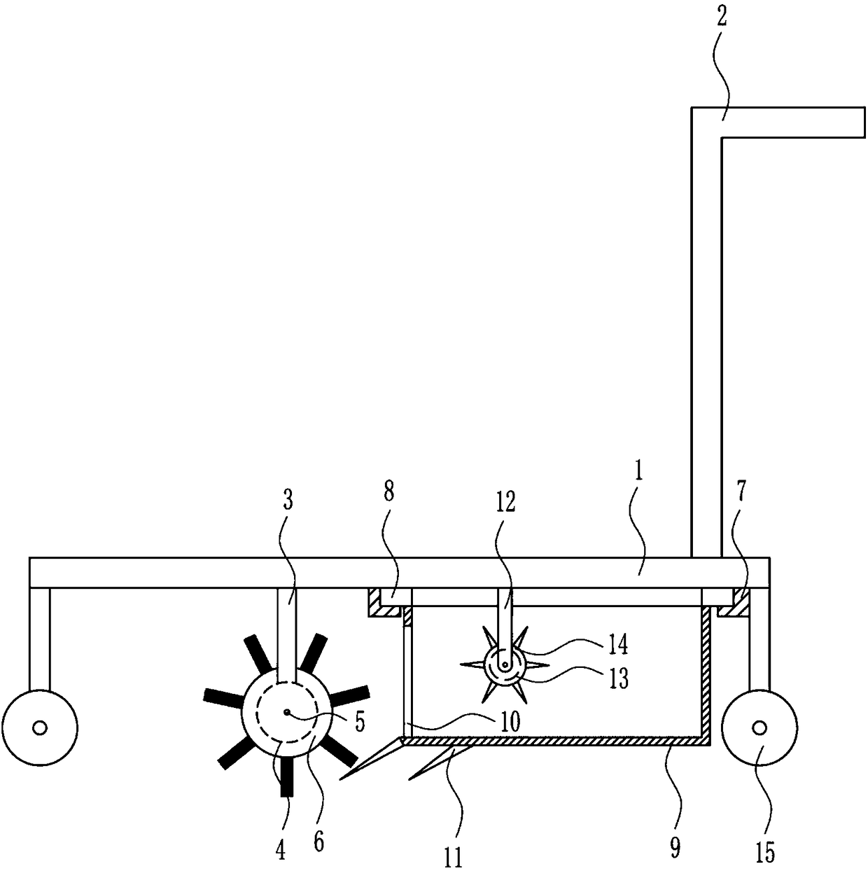
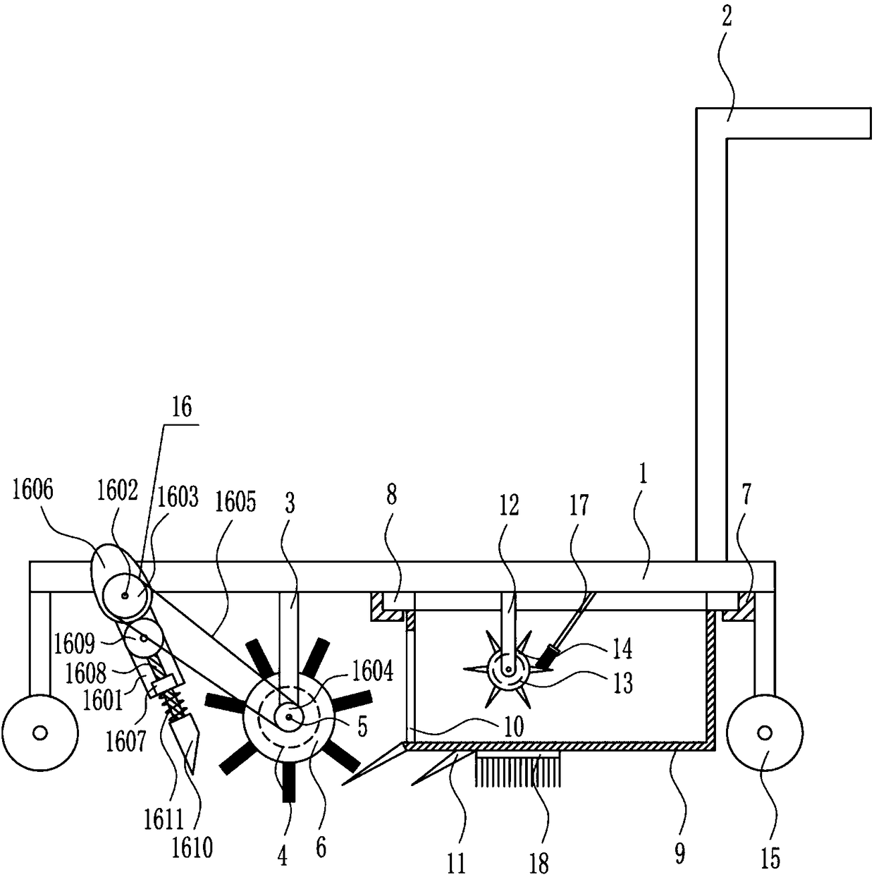
[0020] A kind of excess asphalt cleaning equipment for petroleum asphalt road joint filling, such as Figure 1-2 As shown, it includes a base plate 1, a push handle 2, a first pole 3, a first motor 4, a first rotating shaft 5, a roller brush 6, an L-shaped card plate 7, a first fixing plate 8, a collection box 9, and a guide plate 11. The second support rod 12, the second motor 13, the toggle wheel 14 and the travel wheel 15, the push handle 2 is provided on the right side of the top of the base plate 1, the travel wheel 15 is provided at the bottom of the base plate 1, and the middle of the bottom of the base plate 1 is to the left The position is vertically connected with the first pole 3, the bottom of the first pole 3 is installed with the first motor 4, the output shaft of the first motor 4 is connected with the first rotating shaft 5, and the first rotating shaft 5 is provided with a roller Brush 6, the middle and the right side of the bottom of the base plate 1 are symm...

Embodiment 2

[0022] A kind of excess asphalt cleaning equipment for petroleum asphalt road joint filling, such as Figure 1-2 As shown, it includes a base plate 1, a push handle 2, a first pole 3, a first motor 4, a first rotating shaft 5, a roller brush 6, an L-shaped card plate 7, a first fixing plate 8, a collection box 9, and a guide plate 11. The second support rod 12, the second motor 13, the toggle wheel 14 and the travel wheel 15, the push handle 2 is provided on the right side of the top of the base plate 1, the travel wheel 15 is provided at the bottom of the base plate 1, and the middle of the bottom of the base plate 1 is to the left The position is vertically connected with the first pole 3, the bottom of the first pole 3 is installed with the first motor 4, the output shaft of the first motor 4 is connected with the first rotating shaft 5, and the first rotating shaft 5 is provided with a roller Brush 6, the middle and the right side of the bottom of the base plate 1 are symm...

Embodiment 3

[0025] A kind of excess asphalt cleaning equipment for petroleum asphalt road joint filling, such as Figure 1-2As shown, it includes a base plate 1, a push handle 2, a first pole 3, a first motor 4, a first rotating shaft 5, a roller brush 6, an L-shaped card plate 7, a first fixing plate 8, a collection box 9, and a guide plate 11. The second support rod 12, the second motor 13, the toggle wheel 14 and the travel wheel 15, the push handle 2 is provided on the right side of the top of the base plate 1, the travel wheel 15 is provided at the bottom of the base plate 1, and the middle of the bottom of the base plate 1 is to the left The position is vertically connected with the first pole 3, the bottom of the first pole 3 is installed with the first motor 4, the output shaft of the first motor 4 is connected with the first rotating shaft 5, and the first rotating shaft 5 is provided with a roller Brush 6, the middle and the right side of the bottom of the base plate 1 are symme...


PUM


Abstract

The invention relates to cleaning equipment, in particular to excessive asphalt cleaning equipment for petroleum asphalt road joint filling. The excessive asphalt cleaning equipment can sufficiently clean petroleum asphalt on the surface of a road and is simple and reliable in structure and capable of reducing labor intensity of an operator. The excessive asphalt cleaning equipment comprises a bottom plate, a push hand, a first supporting rod, a first motor, a first rotating shaft, a roller brush, an L-shaped clamping plate, a first fixing plate and a collecting box, the push hand is arrangedon the right side of the top of the bottom plate, and traveling wheels are arranged at the bottom of the bottom plate. The roller brush is driven through the first motor to rotate to sweep surplus petroleum asphalt on the road into the collecting box, and a prodding wheel is utilized to compact the asphalt collected in the collecting box, so that collecting capacity of the collecting box is increased; by optimizing a knocking mechanism, the petroleum asphalt on the road can be cleaned sufficiently.

Description

technical field [0001] The invention relates to a cleaning device, in particular to a cleaning device for excess asphalt used for joint filling of petroleum asphalt roads. Background technique [0002] Petroleum, one of the main objects of geological exploration, is a viscous, dark brown liquid known as the "blood of industry." There are oil reserves in parts of the upper crust. The main component is a mixture of various alkanes, naphthenes and aromatic hydrocarbons. [0003] The oil-forming mechanism of petroleum has two theories of biosedimentary oil and petrochemical oil. The former is more widely accepted. It is believed that oil is formed by organisms in ancient oceans or lakes after a long evolution. It belongs to biosedimentary oil and is non-renewable. It is believed that petroleum is generated from the carbon in the earth's crust itself, has nothing to do with biology, and is renewable. Petroleum is mainly used as fuel oil and gasoline, and is also a raw material...

Claims


Application Information

Patent Timeline
Patent Type & Authority Applications(China)
IPC IPC(8): E01C23/09
CPCE01C23/098
Inventor 刘健红尹新陈梦君
Owner 刘健红
Why Eureka
Try Eureka