Bidirectional road monitoring equipment

A technology for monitoring equipment and roads, which is applied in the field of two-way road monitoring equipment, can solve problems such as increased costs and difficult maintenance, and achieve the effects of saving costs, reducing the number of equipment, and reducing the number

Inactive Publication Date: 2018-09-14
郑州神盾智能科技有限公司
View PDF0 Cites 11 Cited by
  • Summary
  • Abstract
  • Description
  • Claims
  • Application Information

AI Technical Summary

Problems solved by technology

[0007] In order to solve the problems in the prior art that the road monitoring devices are respectively installed on both sides of the road, resulting in increased costs and difficult maintenance, a two-way road monitoring device is provided

Method used


Image

  • Bidirectional road monitoring equipment
  • Bidirectional road monitoring equipment
  • Bidirectional road monitoring equipment

Examples


Embodiment 1

[0040] As a basic example:

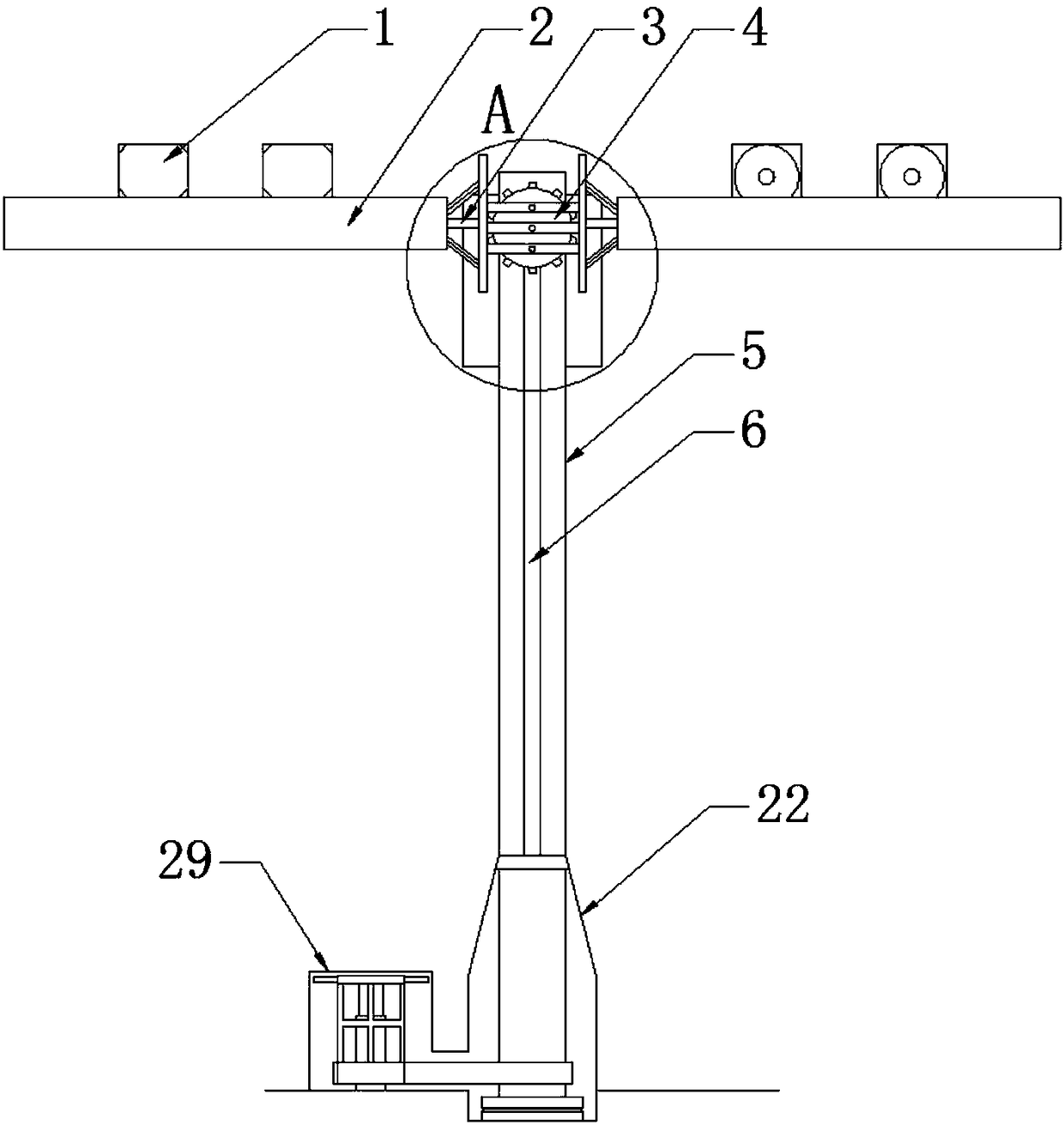
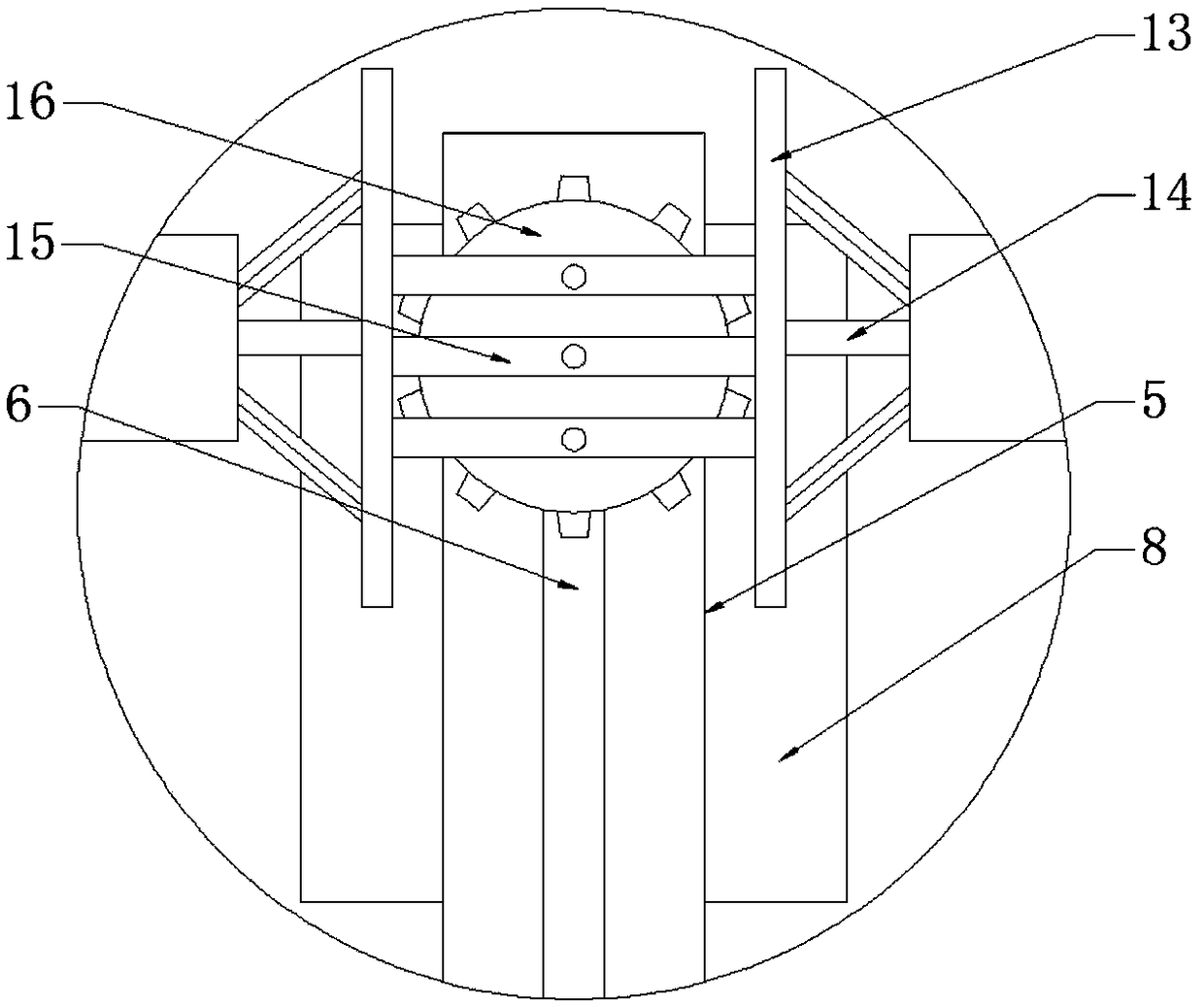
[0041] A two-way road monitoring equipment, comprising a pole 5, a connecting frame 3 is installed on the top of the vertical pole 5, and it is characterized in that a rotating device 4 is connected between the connecting frame 3 and the vertical pole 5, and the connecting frame 3 is also Connected with a movable rack bar 2, a camera 1 is installed on the movable rack bar 2, a central rotating rod 17 connected to the center of the rotating device 4 is installed in the vertical rod 5, and the central rotating rod 17 is connected with a snap-fit Device 11, pulley 10 is installed on the top and bottom in the vertical rod 5, conveyor belt 12 is installed on the pulley 10, the position corresponding to the clamping device 11 on the conveyor belt 12 is connected with a snap-in buckle 20, the vertical The lower end of the rod 5 is covered with a shield shell 22, the bottom of the vertical pole 5 in the shield shell 22 is connected with a rotating chassis ...

Embodiment 2

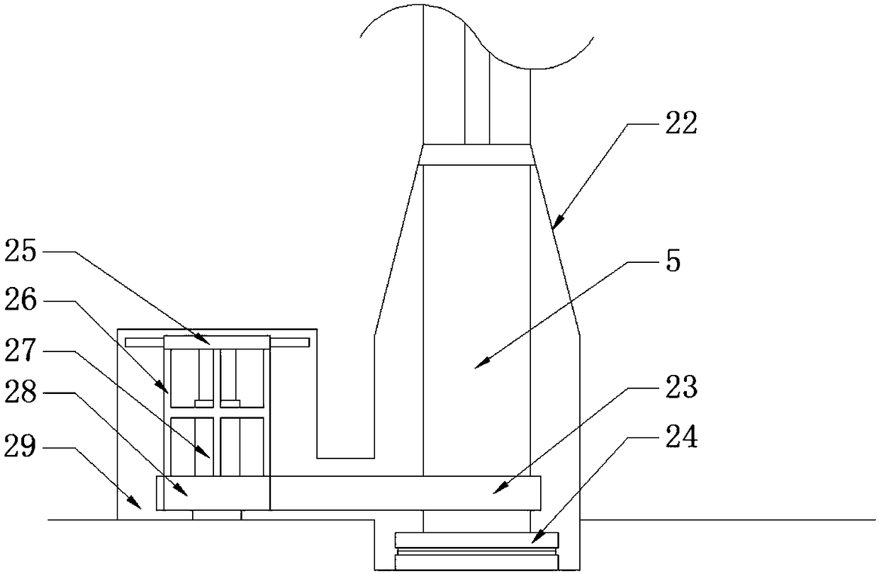
[0044] This embodiment focuses on the improvements compared with the above-mentioned embodiments, and the similarities will not be repeated. In this embodiment, the rotating handle plate 25 is disc-shaped, and the side of the rotating handle plate 25 is connected with multiple A handle, the bottom surface of the rotating handle plate 25 is also connected with a handle support platform 27, the handle intermediate frame 26 includes a plurality of vertical bars connected with the rotating handle plate 25, and a supporting ring is connected between the vertical bars, and the A transmission wheel 28 is also connected between the handle middle frame 26 and the transmission belt 23 .

[0045] The shape of the handle in this embodiment is convenient for maintenance personnel to operate manually without using complex tools, which simplifies the maintenance process. The transmission wheel 28 ensures a more reliable connection between the handle intermediate frame 26 and the transmission ...

Embodiment 3

[0047] This embodiment focuses on the improvements compared with the above-mentioned embodiments, and the similarities will not be repeated. In this embodiment, the rotating chassis 24 includes an upper chassis for supporting rotation and a lower chassis for fixing. The upper surface of the upper chassis is connected to the bottom of the vertical rod 5 , and the lower chassis is installed at the bottom of the shield shell 22 .

[0048] The rotating chassis 24 of this embodiment supports the vertical rod 5 to rotate in the horizontal direction, and cooperates with the shield shell 22 to prevent the vertical rod 5 from tilting or shifting when rotating, which enhances the stability of the equipment operation.


PUM


Abstract

The invention discloses bidirectional road monitoring equipment, belongs to the technical field of monitoring equipment, and solves the problem that cost and maintaining difficulty are increased due to the fact that road monitoring devices are arranged on two sides of a road in the prior art. The bidirectional road monitoring equipment comprises a vertical rod and is characterized in that a connecting rack is mounted at the top of the vertical rod, a rotating device is arranged between the connecting rack and the vertical rod, movable rack rods are connected to the connecting rack, a central rotary rod connected with the center of the rotating device is mounted in the vertical rod, a clamping device is connected to the central rotary rod, a belt wheel is mounted at each of the top and thebottom in the vertical rod, a conveying belt is mounted on the belt wheels, a clamping fastener is connected to the conveying belt, a shield shell sleeves the lower end of the vertical rod, a rotary bottom plate is connected to the bottom of the vertical rod in the shield shell, the shield shell is communicated with a transmission case, a rotary handle plate is mounted in the transmission case, ahandle middle rack is connected below the rotary handle plate, and a transmission belt is connected between the handle middle rack and the vertical rod. The bidirectional road monitoring equipment issimple and efficient in maintenance operation.

Description

technical field [0001] The invention belongs to the technical field of monitoring equipment, and in particular relates to a two-way road monitoring equipment. Background technique [0002] The monitoring device on the road, such as the road traffic monitoring pole, belongs to the camera part of the entire road monitoring system. It is at the forefront of the system and is the "eye" of the entire system. The field angle can cover all parts of the whole being monitored. The camera is like the eyes of the whole system, changing the content it monitors into an image signal and sending it to the monitor in the control center. The whole process can be summarized as camera, signal transmission, command center control, display and recording. [0003] Road monitoring is mainly based on speed ball monitoring. The monitoring points are distributed at road intersections and key road sections where the traffic flow and pedestrian flow are relatively concentrated. Road conditions in ea...

Claims


Application Information

Patent Timeline
Patent Type & Authority Applications(China)
IPC IPC(8): E01F9/696
CPCE01F9/696
Inventor 孙恒
Owner 郑州神盾智能科技有限公司
Why Eureka
Try Eureka