Steam turbine inserting pipe sealing device and using method thereof

A sealing device, steam turbine technology, applied in mechanical equipment, engine components, machines/engines, etc., can solve problems such as poor sealing effect, achieve excellent resilience performance, and make up for the effect of contact surface separation

Active Publication Date: 2018-09-14
NINGBO TIANSHENG SEALING PACKING
View PDF15 Cites 1 Cited by
  • Summary
  • Abstract
  • Description
  • Claims
  • Application Information

AI Technical Summary

Problems solved by technology

[0003] Most of the existing steam turbine cannula are piston ring-type sealing structure, bell-shaped sealing structure or lamination-type sealing structure, but none of the three can avoid the leakage of the cannula and ensure the steam intake efficiency and cylinder efficiency of the cannula.
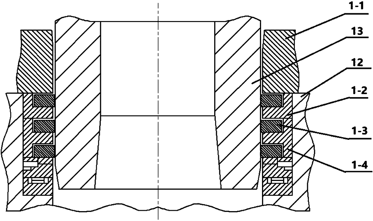
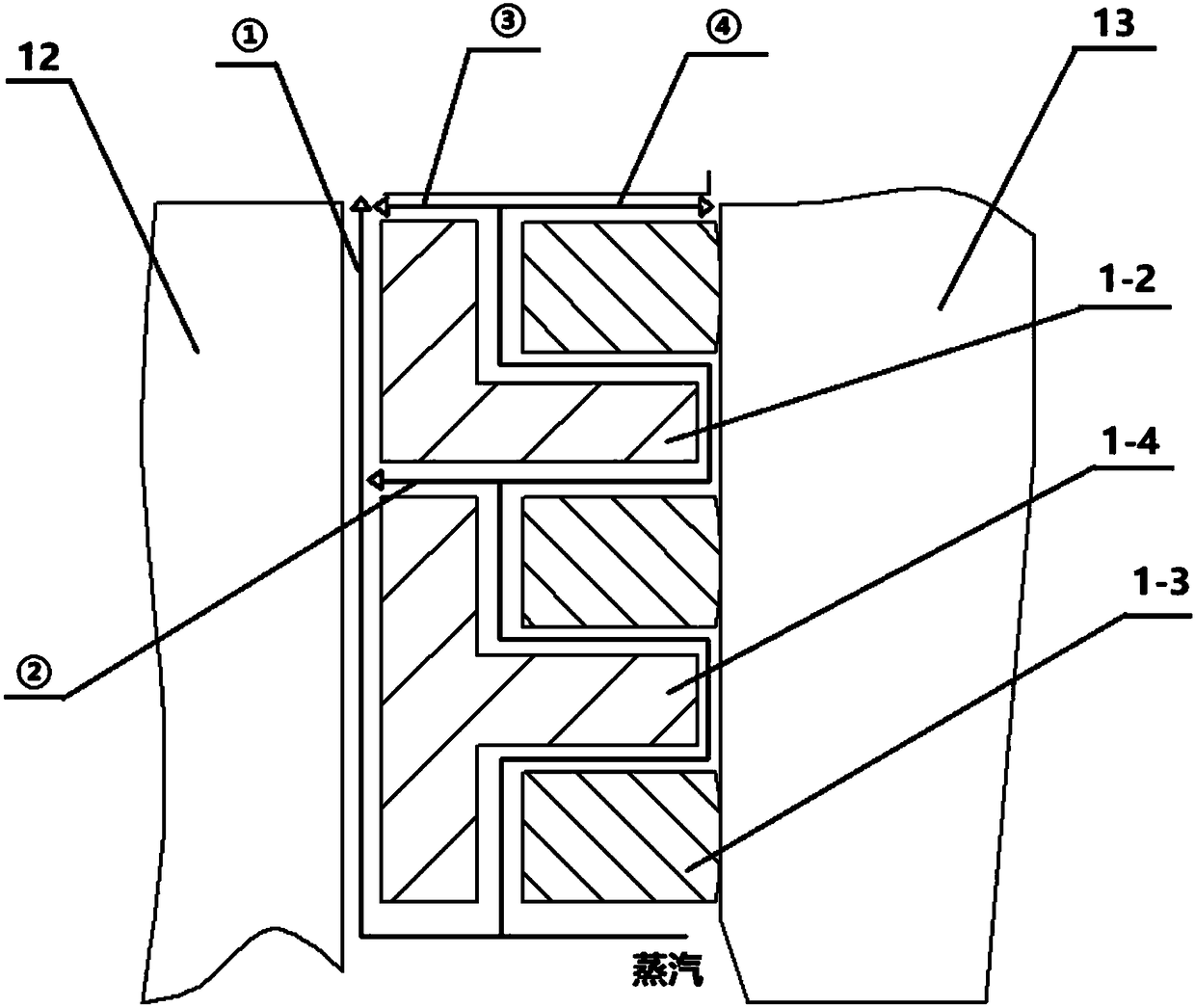
For example, the Chinese patent authorization announcement number CN 2825960Y, the name of the invention is steam turbine high-pressure inner and outer cylinder leak-proof stacked sealing device, which is a laminated sealing structure, through the structure of sealing ring, backing ring, wave spring and guiding backing ring. The sealing device has the characteristics of convenient installation and self-resetting stability. Its sealing structure type is as follows: figure 1 As shown, however, the seal ring of this patent still has the problem of poor sealing effect on the end face of the stack connection and the seal between the seal ring and the high-pressure inner cylinder. For example, in the working state, due to the structure of the stacked sealing device itself , there are 4 leakage channels ①-④ at the gasket ring and the high-pressure inner cylinder, the gasket ring and the gasket ring, and the gasket ring and the sealing ring. The specific leakage channels are as follows: figure 2 shown; Figure 1-2 Among them, 1-1 is the flange, 13 is the inlet pipe, 12 is the high-pressure inner cylinder, 1-2 is the L-shaped backing ring, 1-3 is the sealing ring, and 1-4 is the T-shaped backing ring

Method used


Image

  • Steam turbine inserting pipe sealing device and using method thereof
  • Steam turbine inserting pipe sealing device and using method thereof
  • Steam turbine inserting pipe sealing device and using method thereof

Examples


Embodiment Construction

[0037] In describing the present invention, it should be understood that the terms "center", "longitudinal", "transverse", "length", "width", "thickness", "upper", "lower", "front", " Back", "Left", "Right", "Vertical", "Horizontal", "Top", "Bottom", "Inner", "Outer", "Clockwise", "Counterclockwise", "Axial", The orientation or positional relationship indicated by "radial", "circumferential", etc. is based on the orientation or positional relationship shown in the drawings, and is only for the convenience of describing the present invention and simplifying the description, rather than indicating or implying the referred device or element Must be in a particular orientation, be constructed in a particular orientation, and operate in a particular orientation, and therefore should not be construed as limiting the invention. In addition, the features defined as "first" and "second" may explicitly or implicitly include one or more of these features. In the description of the prese...


PUM


Abstract

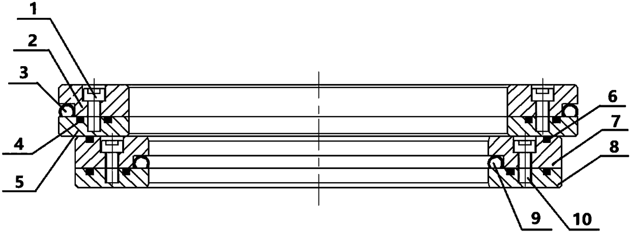
A steam turbine inserting pipe sealing device comprises an outer ring, an inner ring, an outer ring C-shaped ring and an inner ring C-shaped ring. The outer ring and the inner ring are coaxially connected in an abutting mode along the axis of the inner ring; an outer ring C-shaped ring containing groove is formed in the outer diameter surface of the outer ring, and an inner ring C-shaped ring containing groove is formed in the inner diameter surface of the inner ring; the outer ring C-shaped ring is arranged in the outer ring C-shaped ring containing groove, and the inner ring C-shaped ring isarranged in the inner ring C-shaped ring containing groove; and the outer ring C-shaped ring abuts against a high-pressure inner cylinder of a steam turbine, and the inner ring C-shaped ring abuts against a steam inlet inserting pipe of the steam turbine. The steam turbine inserting pipe sealing device creatively achieves sealing in the axial direction and the end face direction through the innerand outer C-shaped rings by utilizing the excellent rebound performance of the C-shaped rings, when the temperature is decreased, the contact surface separation phenomenon caused by decreasing of thetemperature is overcome by utilizing the rebound performance of the C-shaped rings, and thus the whole sealing device forms reliable sealing during equipment operation.

Description

technical field [0001] The invention relates to the technical field of steam turbine sealing, in particular to a steam turbine insertion tube sealing device and a method for using the same. Background technique [0002] In high-parameter and high-power steam turbine units, the high-pressure part generally adopts a multi-layer cylinder structure. Before the steam enters the flow-through part, it needs to pass through independent components such as the outer cylinder and the inner cylinder. Under working conditions, the temperature difference between the outer cylinder and the inner cylinder is large. There is a large differential expansion between the two cylinders. Usually, the steam inlet part adopts a steam inlet intubation structure, one end of which is welded with the outer cylinder as a whole, and the other end needs to move relatively due to the change of temperature difference. The sealing part here is a dynamic seal under high pressure and high temperature condition...

Claims


Application Information

Patent Timeline
Patent Type & Authority Applications(China)
IPC IPC(8): F01D11/00
CPCF01D11/003F01D11/005
Inventor 励行根李征魏世军
Owner NINGBO TIANSHENG SEALING PACKING
Why Eureka
Try Eureka