High-pressure centrifugal blower oil secondary cooling system

A centrifugal blower, secondary cooling technology, applied in mechanical equipment, machines/engines, liquid fuel engines, etc., can solve problems such as adverse effects of system equipment and production up-to-standard operation, potential safety hazards, frequent problems, etc., to achieve small occupied space and investment. Small and easy to construct

Pending Publication Date: 2018-09-14
TAOPU SEWAGE TRAEATMENT PLANT OF SHANGHAI CHENGTOU SEWAGE TREATMENT
View PDF0 Cites 1 Cited by
  • Summary
  • Abstract
  • Description
  • Claims
  • Application Information

AI Technical Summary

Problems solved by technology

However, since these eight centrifugal blowers were installed and put into use, failures and "jumping" caused by "high oil temperature" are

Method used


Image

  • High-pressure centrifugal blower oil secondary cooling system
  • High-pressure centrifugal blower oil secondary cooling system

Examples


Example Embodiment

[0010] The technical solutions of the present invention will be clearly and completely described below in conjunction with the accompanying drawings. Obviously, the described embodiments are part of the embodiments of the present invention, rather than all of them. Based on the embodiments of the present invention, all other embodiments obtained by those of ordinary skill in the art without creative work shall fall within the protection scope of the present invention.
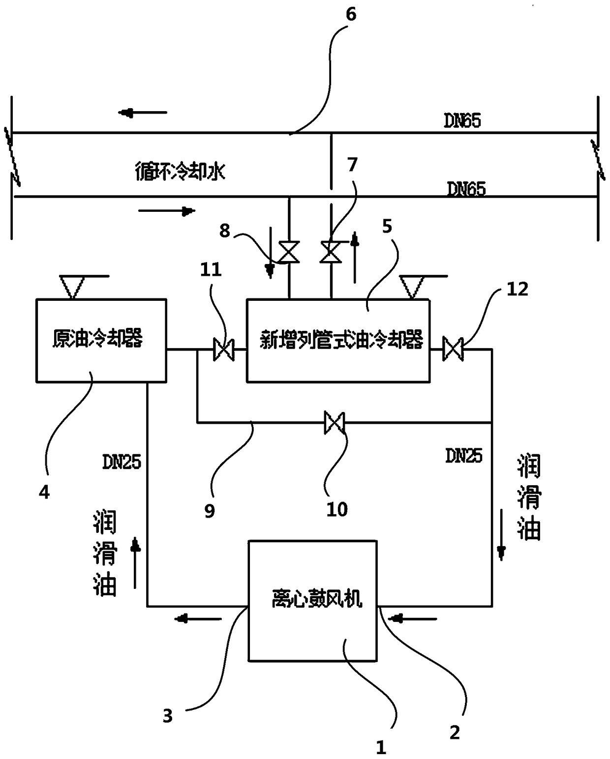
[0011] The present invention discloses a high-pressure centrifugal blower oil secondary cooling system, which is different from the prior art in that it includes a centrifugal blower 1. The centrifugal blower 1 is provided with a lubricant inlet 2 and a lubricant outlet 3, and the lubricant outlet 3 passes through The first pipeline is connected to the inlet of the oil cooler 4, the outlet of the oil cooler 4 is connected to the inlet of the tubular oil cooler 5 through the second pipeline, and the outlet of the tu...


PUM


Abstract

The invention discloses a high-pressure centrifugal blower oil secondary cooling system. The outlet of an oil cooler is connected with the inlet of a shell and tube type oil cooler through a second pipeline; a circulating cooling water loop is arranged at the position of the shell and tube type oil cooler; a filtering device is arranged at the position of the circulating cooling water loop; the process flow of an oil cooling system adopts a primary air-cooling (enhancement) and secondary water-cooling (circulating) scheme; an original air-cooling type heat exchanger is kept and enhanced; and anewly added circulating water-cooling type heat exchanger is connected with the original air-cooling type heat exchanger in series to operate and use. During design and mounting, a necessary controlvalve and a necessary bypass pipeline can be added, so that air cooling and water cooling can be controlled separately and independently. Particularly in the non-high-temperature seasons, the newly added secondary circulating water-cooling heat exchange and primary air-cooling enhanced parts can be stopped according to the operation condition, and only the original primary air-cooling heat exchange is operated, so that hydroelectric resources are saved, the production cost is reduced and the flexibility of overhaul and operation of the oil cooling system are improved to a certain degree.

Description

technical field [0001] The present invention relates to the technical field of centrifugal blower cooling systems, in particular to a high-pressure centrifugal blower oil secondary cooling system, especially the connection structure of the cooling system. Background technique [0002] KA22SV-GL225 high-pressure centrifugal blower, the maximum blowing volume of a single unit is 20671m2 / h, and the maximum exhaust pressure is 1.750bar. Since the installation and operation of the blower unit, it has been playing an important role in the production process of the integrated biological reaction tank, and it is the key equipment to ensure that the sewage treatment reaches the standard production and operation. The 8 blower units are designed to operate in parallel, with 3 on and 5 on standby or 4 on and 4 on standby, and they are switched regularly every month. Over the years, 8 high-pressure blowers have operated alternately and efficiently, and the overall condition of the equip...

Claims


Application Information

Patent Timeline
IPC IPC(8): F04D29/58F04D29/063F04D29/70F04D25/08
CPCF04D29/582F04D25/08F04D29/063F04D29/703
Inventor 陈广姚杰汪喜生肖建军季鸿先程建忠徐耀钱春林彭争梁郭志义裘湛
Owner TAOPU SEWAGE TRAEATMENT PLANT OF SHANGHAI CHENGTOU SEWAGE TREATMENT
Why Eureka
Try Eureka