a pressure control system

A technology of pressure control and hydraulic cylinder, which is applied in the direction of fluid pressure actuators, servo motors, servo motor components, etc. It can solve the problems that the ball cannot be accurately aligned with the valve seat, the degree of firmness is not enough, and the function is single, so as to achieve convenience in daily life. The effect of maintenance

Inactive Publication Date: 2019-09-06
CHANGSHA UNIVERSITY OF SCIENCE AND TECHNOLOGY
View PDF10 Cites 0 Cited by
  • Summary
  • Abstract
  • Description
  • Claims
  • Application Information

AI Technical Summary

Problems solved by technology

[0004] 1. In the pressure control circuit of the prior art, the main drive oil circuit is the main path through which the hydraulic fluid passes, and various abnormal conditions are prone to occur. When abnormal conditions occur, such as overpressure conditions, the pipeline ruptures or other faults
[0005] 2. The gate valve is an important part of the pressure control system. The gate valve in the prior art often only has a cut-off function, and the single function cannot adapt to various complex working conditions.
[0006] 3. Due to the dynamic sealing of the check valve in the prior art, such as the cooperation of the spring, the ball and the valve seat, it is difficult to achieve good sealing
And after a long time of use, the performance of the spring decreases, and the ball cannot be accurately aligned with the valve seat.
[0007] 4. The size of the gate valve in the prior art cannot be adjusted in real time when it is specifically adapted to the working environment, especially for the driving parts. When the size of the cut-off body cannot be adjusted, the adjustment of the size of the driving parts is often particularly important
[0008] 5. The adjustment scheme of the valve stem in the prior art is often flexible enough, but not strong enough to be used for a long time under heavy load
[0009] 6. Due to the long-term use of the driving source of the prior art, more maintenance is required, and there is a lack of maintenance means in the prior art
[0010] 7. The existing technology includes a gate valve pressure control system, which often has a single function, cannot realize the energy storage function, and cannot recycle excess energy

Method used


Image

  • a pressure control system
  • a pressure control system
  • a pressure control system

Examples


Embodiment Construction

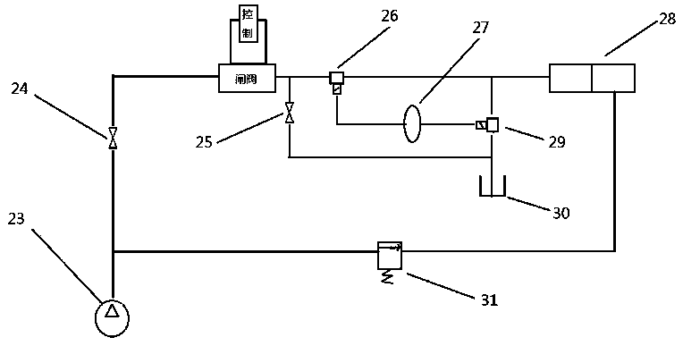
[0037] As shown in the figure: a pressure control system, the pressure control system includes a pump, a first switch, a second switch, a first three-way valve, an accumulator, a hydraulic cylinder, a second three-way valve, an oil tank, and a solenoid valve , gate valve; the liquid in the pump is connected to the first chamber of the hydraulic cylinder through the main road, and connected to the second chamber of the hydraulic cylinder through the auxiliary road; the main road includes the first switch, the gate valve, the first tee valve; the auxiliary circuit includes the solenoid valve;

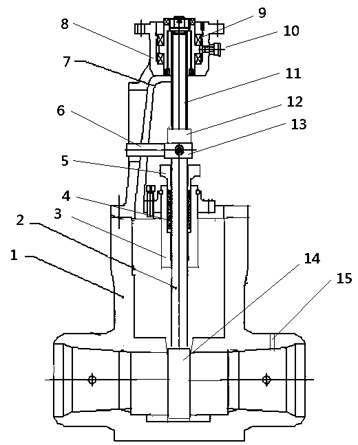
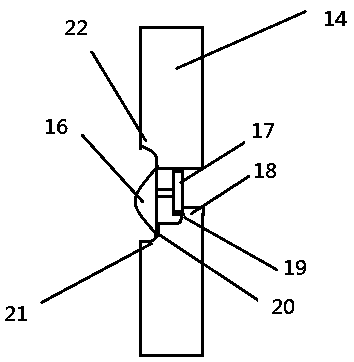
[0038] As shown in the figure: after the liquid is output from the pump, it is connected to the gate valve through the first switch, and the gate valve includes a valve body, a lower valve stem, a stuffing box, packing, a packing gland, a stem support frame, a bracket, and a flange. Lan, bearing, grease nipple, upper valve stem, support ring, support seat, ram, sampling hole, umbrella win...


PUM


Abstract

The invention discloses a pressure control system. The pressure control system comprises a pump, a first switch, a second switch, a first three-way valve, an energy accumulator, a hydraulic cylinder,a second three-way valve, an oil tank, an electromagnetic valve and a brake valve; liquid in the pump is connected with a first cavity of the hydraulic cylinder through a main circuit and connected with a second cavity of the hydraulic cylinder through an auxiliary circuit; the main circuit comprises the first switch, the brake valve and the first three-way valve; the auxiliary circuit comprises the electromagnetic valve; liquid released through decompression is delivered out from the brake valve and then connected to the energy accumulator through the first three-way valve, the downstream endof the energy accumulator is connected to the second three-way valve, and the three ends of the second three-way valve are connected with the main circuit, the energy accumulator and the oil tank; and the main circuit, a branch circuit including the energy accumulator and a branch including the second switch are connected in parallel.

Description

technical field [0001] The invention relates to the related field of fluid control, in particular to a pressure control system. Background technique [0002] In the pressure control system, the hydraulic cylinder execution system is a commonly used execution system, which controls the reciprocating motion of the hydraulic cylinder through the main hydraulic drive circuit and the hydraulic drive branch circuit for driving. Gate valve is one of the common components. [0003] In actual use, the existing pressure control system and the gate valve therein have the following problems: [0004] 1. In the pressure control circuit of the prior art, the main drive oil circuit is the main path through which the hydraulic fluid passes, and various abnormal conditions are prone to occur. When abnormal conditions occur, such as overpressure conditions, the pipeline ruptures or other failures. [0005] 2. The gate valve is an important part of the pressure control system. The gate valv...

Claims


Application Information

Patent Timeline
Patent Type & Authority Patents(China)
IPC IPC(8): F15B13/02F15B11/08F15B1/04
Inventor 李方义严宇飞张遥王鑫
Owner CHANGSHA UNIVERSITY OF SCIENCE AND TECHNOLOGY
Why Eureka
Try Eureka