Angling cylinder with pressure maintaining function

A technology of rotary oil cylinder and function, applied in the field of rotary oil cylinder and rotary oil cylinder with pressure maintaining function, can solve the problems of falling off, affecting the machining accuracy of workpiece, and oil return.

Pending Publication Date: 2018-09-14
玉环广越机械有限公司
View PDF9 Cites 2 Cited by
  • Summary
  • Abstract
  • Description
  • Claims
  • Application Information

AI Technical Summary

Problems solved by technology

However, in the process of processing, when the power of the machine tool is suddenly cut off or the oil supply of the hydraulic station is suddenly interrupted, the oil in the oil chamber 2 will flow back due to insufficient oil supply pressure, which will As a result, the workpiece cannot be effectively clamped or even falls off directly, which affects the subsequent machining accuracy of the workpiece

Method used


Image

  • Angling cylinder with pressure maintaining function
  • Angling cylinder with pressure maintaining function
  • Angling cylinder with pressure maintaining function

Examples


Embodiment 1

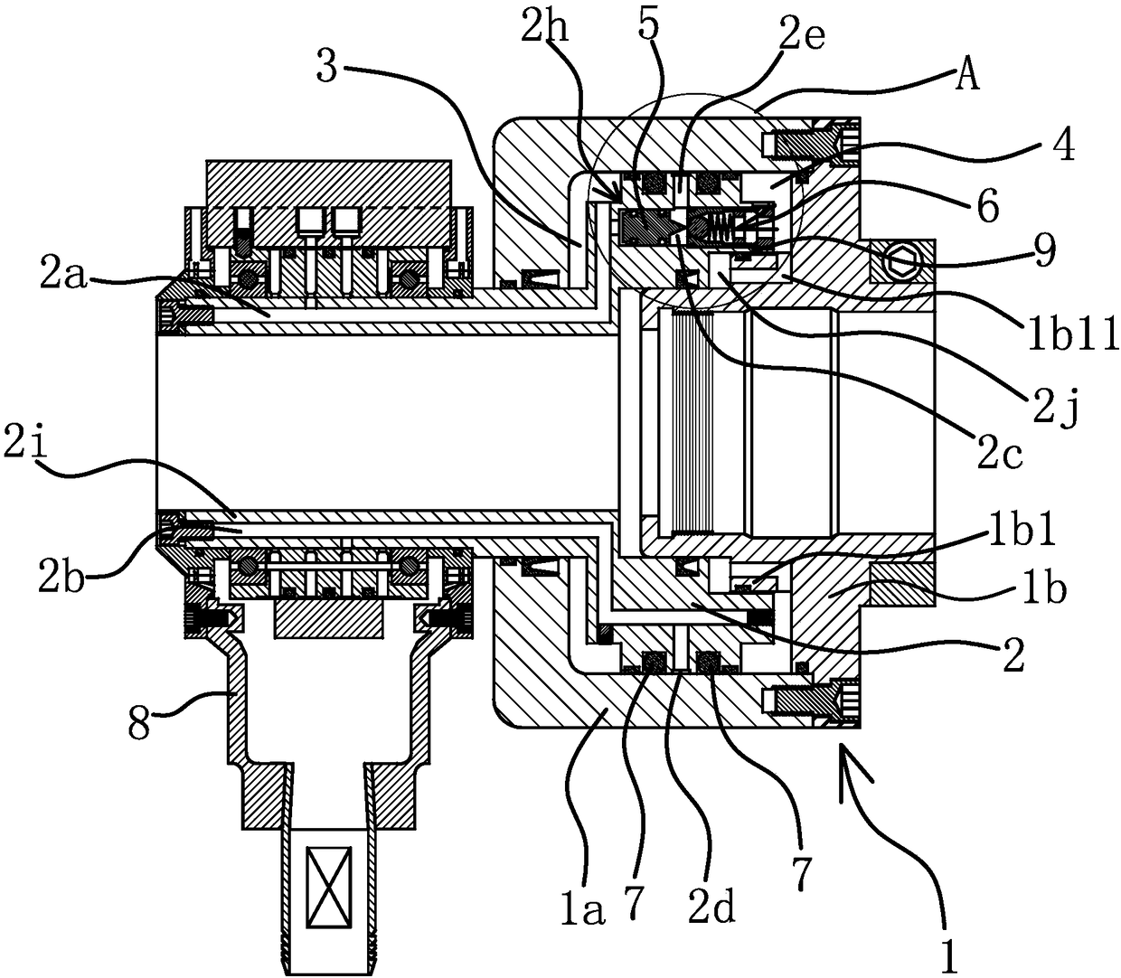
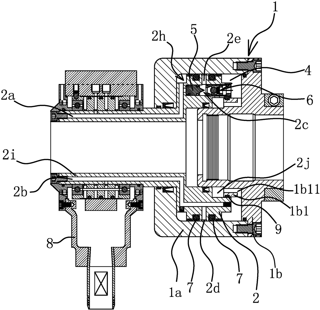
[0034] Such as figure 1 and Figure 5 As shown, a rotary oil cylinder with a pressure maintaining function includes a cylinder body 1 and a large piston 2 arranged in the cylinder body 1 and capable of moving back and forth. The rear end of the large piston 2 forms an oil chamber 3 with the inner wall of the cylinder body 1, and the piston The front end and the inner wall of the cylinder body 1 form an oil chamber 2 4 . The big piston 2 is provided with an oil passage one 2a and an oil passage two 2b, the outlet of the oil passage one 2a communicates with the oil chamber one 3, and the outlet of the oil passage two 2b communicates with the oil chamber two 4.

[0035] Such as figure 1 As shown, a protruding fitting part 2i is provided on the rear end surface of the large piston 2, and the fitting part 2i extends out of the rear end of the cylinder body 1, and the inlet of the oil passage 2a and the inlet of the oil passage 2b are both located at the ends extending to the cyli...

Embodiment 2

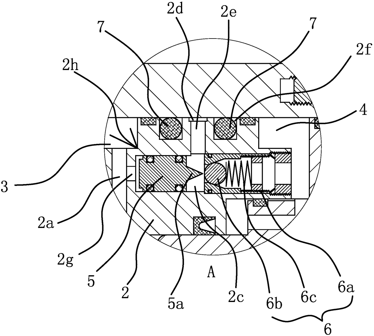
[0047] The structure and principle of this embodiment are basically the same as that of Embodiment 1, the difference is that in this embodiment, the check valve 6 includes a valve body 6a fixed in the positioning hole 2c and a sealing head arranged in the valve body 6a With the spring 6c, the valve body 6a is cylindrical with both ends open and the sealing head closes the rear port of the valve body 6a under the elastic force of the spring 6c, the small piston 5 is cylindrical, and the rear end of the sealing head is provided with a protruding Connecting rod, the end of the connecting rod extends to the outside of the rear port of the valve body 6a.

[0048]Adopt sealing head and spring 6c to form the non-return structure of check valve 6, and arrange the connecting rod extending to the outside of the rear port of valve body 6a at the rear end of sealing head, oil passage-2a when oil enters in oil passage-2a The oil inside pushes the small piston 5 to move forward, and when th...


PUM


Abstract

The invention provides an angling cylinder with a pressure maintaining function, belongs to the technical field of machinery and solves the problem that the conventional angling cylinder does not havethe pressure maintaining function and is poor in stability. The angling cylinder comprises a cylinder body and a big piston arranged in the cylinder body and capable of moving forwards and backwards,wherein an oil chamber I is formed by the rear end of the big piston and the inner wall of the cylinder body, an oil chamber II is formed by the front end of the big piston and the inner wall of thecylinder body, an oil channel I and an oil channel II are formed in the big piston, an outlet of the oil channel I communicates with the oil chamber I, a positioning hole is formed in the big piston,the oil channel I communicates with the positioning hole, the oil chamber II communicates with the oil channel II through the positioning hole, a check valve and a small piston are arranged in the positioning hole from front to back, the check valve is closed in front-to-back direction and can be opened when the small piston moves forwards, the communication part of the oil channel I and the positioning hole is located at the rear of the small piston, and the communication part of the oil channel II and the positioning hole is located between the small piston and the check valve. The angling cylinder has the advantages that pressure maintaining can be realized, normal work of the angling cylinder can be guaranteed, stability is good, and the like.

Description

technical field [0001] The invention belongs to the technical field of machinery and relates to a rotary oil cylinder, in particular to a rotary oil cylinder with a pressure maintaining function. Background technique [0002] The existing lathe spindle box usually includes a box body and a rotary oil cylinder. A hollow piston is arranged in the rotary oil cylinder. A main shaft and a drawing tube are arranged in the box body. The drawing tube is passed through the main shaft. There is a collet / chuck, the cylinder body of the rotary cylinder is connected to the main shaft, one end of the pull tube extends into the hollow piston and connects with the hollow piston, and the other end of the pull tube is connected to the collet / chuck, driven by the hollow piston The pull tube moves to realize the collet / chuck to clamp or loosen the workpiece, and the spindle rotates to drive the collet / chuck and the workpiece to rotate. However, because the pistons of traditional rotary cylinde...

Claims


Application Information

Patent Timeline
Patent Type & Authority Applications(China)
IPC IPC(8): F15B15/14F15B20/00B23B19/00B23Q3/08
CPCF15B15/1447F15B20/00B23Q1/70B23Q3/08B23Q3/082
Inventor 郭必龙
Owner 玉环广越机械有限公司
Why Eureka
Try Eureka