Hydraulic movable arm potential energy recovery system and method

A boom potential energy recovery system technology, applied to fluid pressure actuation system components, fluid pressure actuation devices, mechanical equipment, etc., can solve the problems of multiple energy conversion links, low emission energy waste, energy waste, etc., to achieve The effect of secondary conversion and utilization of energy and reduction of energy loss and waste

Pending Publication Date: 2018-09-14
CHANGAN UNIV
View PDF0 Cites 2 Cited by
  • Summary
  • Abstract
  • Description
  • Claims
  • Application Information

AI Technical Summary

Problems solved by technology

As a member of construction machinery, hydraulic excavators have the characteristics of high energy consumption and low emissions, resulting in a large amount of energy waste and loss, resulting in serious environmental pollution and energy waste. Therefore, the hydraulic system of hydraulic excavators is improved to achieve energy saving and emission reduction. The purpose has very necessary research significance
[0003] During the operation of the hydraulic excavator, the boom frequently rises and falls, and more downward potential energy will be generated during the l

Method used


Image

  • Hydraulic movable arm potential energy recovery system and method
  • Hydraulic movable arm potential energy recovery system and method
  • Hydraulic movable arm potential energy recovery system and method

Examples


Embodiment Construction

[0025] The present invention is further described below in conjunction with accompanying drawing:

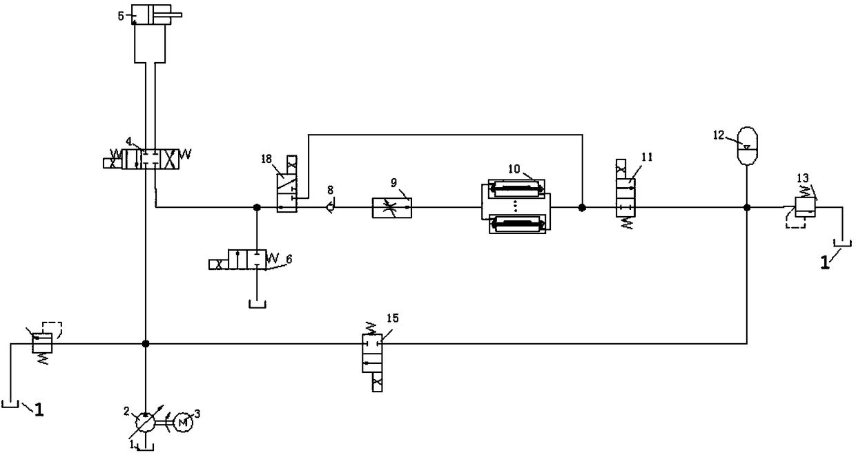
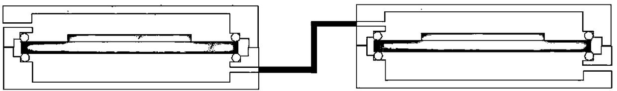
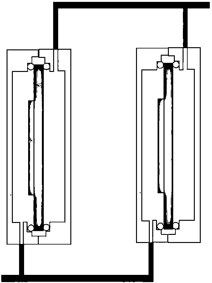
[0026] see Figure 1-Figure 3 , a hydraulic boom potential energy recovery system, including a fuel tank 1, a variable pump 2, a motor 3, a three-position four-way reversing valve 4, a hydraulic cylinder 5, a first two-position two-way reversing valve 18, and a piezoelectric transducer device 10 and accumulator 12; oil tank 1 and motor 3 are both connected to the variable pump 2, the output of the variable pump is connected to the first inlet of the three-position four-way reversing valve 4, and the first outlet of the three-position four-way reversing valve 4 is connected to The inlet of the hydraulic cylinder 5, the outlet of the hydraulic cylinder 5 is connected to the second inlet of the three-position four-way reversing valve 4, and the second outlet of the three-position four-way reversing valve 4 is connected to the inlet of the first two-position two-way reversing valve ...


PUM


Abstract

The invention discloses a hydraulic movable arm potential energy recovery system and method. The hydraulic movable arm potential energy recovery system comprises an oil tank, a variable pump, a motor,a three-position four-way reversing valve, a hydraulic cylinder, a first two-position two-way reversing valve, a piezoelectric transducer and an energy accumulator. The oil tank and the motor are both connected to the variable pump, the output end of the variable pump is connected with a first inlet of the three-position four-way reversing valve, a first outlet of the three-position four-way reversing valve is connected with an inlet of the hydraulic cylinder, and an outlet of the hydraulic cylinder is connected with a second inlet of the three-position four-way reversing valve; a second outlet of the three-position four-way reversing valve is connected with an inlet of the first two-position two-way reversing valve, and a first outlet of the first two-position two-way reversing valve isconnected with the piezoelectric transducer; and the piezoelectric transducer is connected with an inlet of the energy accumulator, and an outlet of the energy accumulator is connected to the variablepump. According to the hydraulic movable arm potential energy recovery system and method, a piezoelectric power generating technology is applied to a hydraulic system with the energy accumulator forenergy recovery so as to achieve secondary energy recovery, hydraulic energy is rapidly converted into electric energy to be stored, and then recovery and reusing of the energy are achieved.

Description

technical field [0001] The invention belongs to the technical field of hydraulic vibration energy recovery and power generation, and in particular relates to a hydraulic boom potential energy recovery system and method. Background technique [0002] As an important part of the equipment industry, construction machinery is widely used in national defense construction projects, transportation construction, energy industry construction and production, mining and other raw material industry construction and production, agriculture, forestry and water conservancy construction, industrial and civil construction, urban construction, environmental protection, etc. application in a field. As a member of construction machinery, hydraulic excavators have the characteristics of high energy consumption and low emissions, resulting in a large amount of energy waste and loss, resulting in serious environmental pollution and energy waste. Therefore, the hydraulic system of hydraulic excavat...

Claims


Application Information

Patent Timeline
IPC IPC(8): F15B21/14F15B21/08F15B1/02
CPCF15B1/02F15B21/087F15B21/14
Inventor 高永昌秦银平陈瑱贤张静李昆鹏陈世斌
Owner CHANGAN UNIV
Why Eureka
Try Eureka