Electro-hydraulic servo valve with acceleration bias drift inhibition function

An electro-hydraulic servo valve, zero offset drift technology, applied in the direction of servo motor components, valve details, valve devices, etc., can solve the problems of high computational complexity, unsuitable for production application, high hardware cost, etc., to achieve simple calculation method and structure Simple, low-cost-to-manufacture effect

Inactive Publication Date: 2018-09-14
TONGJI UNIV
View PDF8 Cites 4 Cited by
  • Summary
  • Abstract
  • Description
  • Claims
  • Application Information

AI Technical Summary

Problems solved by technology

This method can also effectively suppress the zero offset drift, but the calculation complexity is high, and the requirements for hardware cost are also high, so it is not suitable for actual production applications

Method used


Image

  • Electro-hydraulic servo valve with acceleration bias drift inhibition function
  • Electro-hydraulic servo valve with acceleration bias drift inhibition function
  • Electro-hydraulic servo valve with acceleration bias drift inhibition function

Examples


Embodiment 1

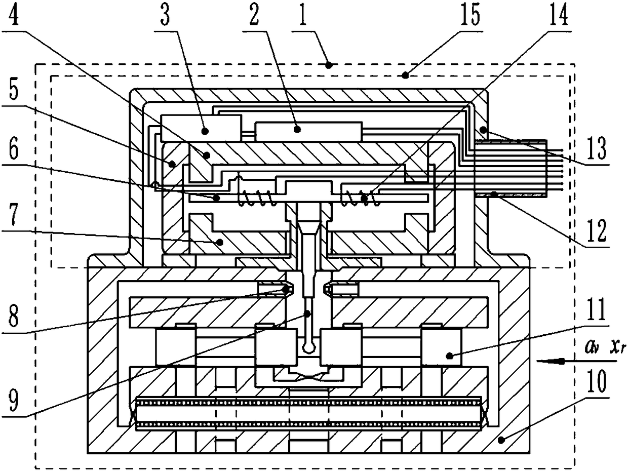
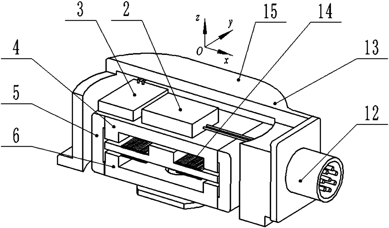
[0046] Such as figure 1 As shown, this embodiment provides an electro-hydraulic servo valve with acceleration zero offset drift suppression function, including an electro-hydraulic servo valve body 1, an accelerometer 2, and a current amplifier 3. The electro-hydraulic servo valve body in this embodiment 1. The nozzle baffle type electro-hydraulic servo valve is used, mainly including: upper guide magnet 4, permanent magnet 5, armature baffle assembly 6, lower guide magnet 7, nozzle 8, feedback lever 9, valve body 10, main valve core 11. Current input port 12, torque motor cover 13 and control coil 14. The upper magnet guide 4 , the permanent magnet 5 , the armature baffle 6 , the lower magnet guide 7 , the current input port 12 , the torque motor cover 13 and the control coil 14 constitute the torque motor 15 of the electro-hydraulic servo valve body 1 . The accelerometer 2 and the current amplifier 3 form a zero offset drift suppression device.

[0047] The accelerometer 2...

Embodiment 2

[0065] The structure of the electro-hydraulic servo valve in this embodiment is basically the same as that in Embodiment 1, the difference is that the body 1 of the electro-hydraulic servo valve is connected in series with double coils. At this time, the superposition relationship between the control current and the feedback current is as follows Figure 5 shown. Pin A of the current terminal is the positive pole of the control current Δi, pin D is the negative pole of the control current Δi, pin B and pin C are short-circuited. At this time, the positive pole of the amplifier feedback current Δi" is connected to pin D, and the negative pole of the amplifier feedback current Δi" is connected to pin A.

Embodiment 3

[0067] The structure of the electro-hydraulic servo valve in this embodiment is basically the same as that in Embodiment 1, the difference is that the body 1 of the electro-hydraulic servo valve adopts a double-coil parallel connection method. At this time, the superposition relationship between the control current and the feedback current is as follows Figure 6 shown. Pin A of the current terminal is the positive pole of the control current Δi, pin D is the negative pole of the control current Δi, pin B and pin D are short-circuited, and pin A and pin C are short-circuited. At this time, the positive pole of the amplifier feedback current Δi" is connected to pin D, and the negative pole of the amplifier feedback current Δi" is connected to pin A.


PUM


Abstract

The invention relates to an electro-hydraulic servo valve with the acceleration bias drift inhibition function. The electro-hydraulic servo valve comprises an electro-hydraulic servo valve body, an accelerometer arranged in the electro-hydraulic servo valve body and used for detecting the axial acceleration of a main valve element in the electro-hydraulic servo valve body and converting the acceleration into measuring current and a current amplifier which is arranged in the electro-hydraulic servo valve body and connected with the accelerometer and used for amplifying the measuring current toobtain feedback current, and overlapping the feedback current to the control current of a control coil of the electro-hydraulic servo valve body so as to achieve inhibition of the acceleration bias drift of the electro-hydraulic servo valve body. Compared with the prior art, the valve has the beneficial effects that the inhibition of the acceleration bias drift can be effectively achieved, the valve is simple, the application range is wide, and the implementation cost is low.

Description

technical field [0001] The invention relates to the technical field of electro-hydraulic servo valves, in particular to an electro-hydraulic servo valve with the function of suppressing acceleration zero offset drift. Background technique [0002] Electro-hydraulic servo valves first appeared during World War II, and are widely used in the aerospace field due to their high precision, fast response, small size, and light weight. As the core component of the attitude control system of the aircraft, the reliability of the electro-hydraulic servo valve directly determines the success or failure of the flight mission. When the aircraft is working, the electro-hydraulic servo valve is often in an acceleration environment. In the ground-moon transfer orbit, when the attitude is changed by pitching, yawing and rolling, the space attitude of the electro-hydraulic servo valve changes accordingly, so it works under the acceleration environment. When the acceleration direction is the s...

Claims


Application Information

Patent Timeline
Patent Type & Authority Applications(China)
IPC IPC(8): F16K31/04F15B13/02
CPCF15B13/02F16K31/046
Inventor 李长明訚耀保李双路
Owner TONGJI UNIV
Why Eureka
Try Eureka