
Fast generalized decision feedback equalizer precoder implementation for multi-user multiple-input multiple-output wireless transmission systems

a general decision feedback and precoder technology, applied in the field of multi-user multi-input multi-output (mimo) communication systems, can solve the problems of extensive computational cost, achieve the effect of reducing computational cost, no capacity loss, and improving the performance of various mu-mimo wireless systems

Inactive Publication Date: 2010-09-16
HITACHI LTD
View PDF6 Cites 20 Cited by
  • Summary
  • Abstract
  • Description
  • Claims
  • Application Information

AI Technical Summary

Benefits of technology

[0010]A technique is used to realize a GDFE Precoder for multi-user (MU) MIMO systems, which significantly reduces the computational cost while resulting in no capacity loss. The technique is suitable for improving the performance of various MU-MIMO wireless systems including presently planned future “4G” cellular networks.
[0011]The described implementation of a GDFE Precoder relaxes the requirement for knowledge of the covariance matrix (Szz) corresponding to “Least Favorable Noise.” This is the key component in conventional design of a GDFE Precoder and requires extensive computational cost. It also provides a uniform framework for realizing a GDFE Precoder. Unlike conventional GDFE Precoder design, the proposed method does not require channel reduction when the Input Covariance Matrix (Sxx) for downlink channel is rank deficient.
[0012]The described implementation of a GDFE Precoder achieves significant improvement in computational cost over conventional GDFE Precoders.

Problems solved by technology

The described implementation of a GDFE Precoder relaxes the requirement for knowledge of the covariance matrix (Szz) corresponding to “Least Favorable Noise.” This is the key component in conventional design of a GDFE Precoder and requires extensive computational cost.

Method used


Image

  • Fast generalized decision feedback equalizer precoder implementation for multi-user multiple-input multiple-output wireless transmission systems
  • Fast generalized decision feedback equalizer precoder implementation for multi-user multiple-input multiple-output wireless transmission systems
  • Fast generalized decision feedback equalizer precoder implementation for multi-user multiple-input multiple-output wireless transmission systems

Examples


example-1

Using Eq. (12) to Compute C

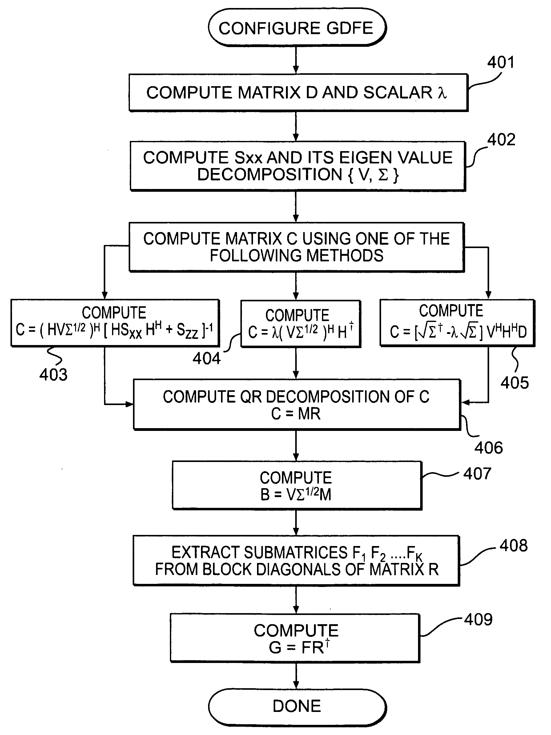
[0054]The following numerical example illustrates the computation of various matrices involved in the design of GDFE Precoder for the case when Szz is known beforehand, i.e. C is computed using equation (12).

[0055]Consider a BS with 4 antennas and 2 users with 2 antennas each, so that channel matrices associated with both the users are of dimension 2×4. Let the overall channel matrix be the following:

H=[H1H2]=[0.81561.1908-1.6041-0.80510.7119-1.20250.25730.52871.2902-0.0198-1.05650.21930.6686-0.15671.4151-0.9219](27)

[0056]For fixed transmit power of 20, the optimal input covariance matrix Sxx for the downlink channel can be computed by first computing the optimal input covariance matrix D for the equivalent Uplink / MAC channel as described in [6] and then using the equation (10):

Sxx=[6.0504-0.8646-0.5495-0.9077-0.86464.0316-1.5417-2.4559-0.5495-1.54175.7981-1.3812-0.9077-2.4559-1.38124.1262](28)

[0057]The Eigen Value Decomposition (EVD) of Sxx can be compute...

example-2

Using Eq. (22) to Compute C

[0064]The following numerical example illustrates the computation of various matrices involved in the design of GDFE Precoder when Szz is unknown. The same system as in Example-1 with transmit power fixed to 20 is assumed so that matrices H, Sxx, V, and Y are given by Equations (27)-(30) respectively.

[0065]Following the details outlined in B.1, compute the matrix C and its QR Decomposition:

C=(VΣ1 / 2)HH-1=[-0.37460.60160.4650-0.53060.3008-0.52900.0216-0.7932-0.09900.3554-0.8802-0.2985-0.8715-0.4815-0.0924-0.0118]M[1.82671.3854-1.9276-0.059901.6511-0.5381-0.384800-1.5611-0.37120001.4027]R(37)

[0066]Next, the method computes the transmit filter matrix B as

B=VΣ1 / 2M=[-0.05080.2239-2.26230.93780.5568-1.91450.0891-0.2198-0.62200.44881.12141.9849-1.10571.1097-0.0002-1.2931](38)

[0067]Also, the effective feedforward filter is computed as:

F=[F100F2]=BlockDiag(R)=[1.82671.38540001.65110000-1.5611-0.37120001.4027](39)

[0068]Therefore, the two users employ the following fe...

example-3

Using Eq. (22) to Compute C

[0070]Consider the same system as in previous example but fix the transmit power to 10 instead of 20 as in pervious two examples. In this case, the matrices associated with the GDFE Precoder can be shown to be:

B=[-0.14160-1.6054-0.67151.387300.06170.1574-0.528400.8176-1.4211-1.08340-0.01060.9258](42)

[0071]From Eq. (42), it is apparent that the 2nd column of B is zero, implying that the second element in x1 is assigned 0 transmit power. It is therefore suggested to transmit only 1 symbol to UT-1 and 2 symbols to UT-2, that is set u1=[u110]T, u2=[u21 u22]T so that u=[u1Tu2T]T. The rest of matrices associated with the GDFE precoder can be shown to be:

F1=[0.6711-0.510600],F2=[-1.1131-0.25320-1.0043]and(43)G=[10-0.32460.2913010000100001](44)


PUM


Abstract

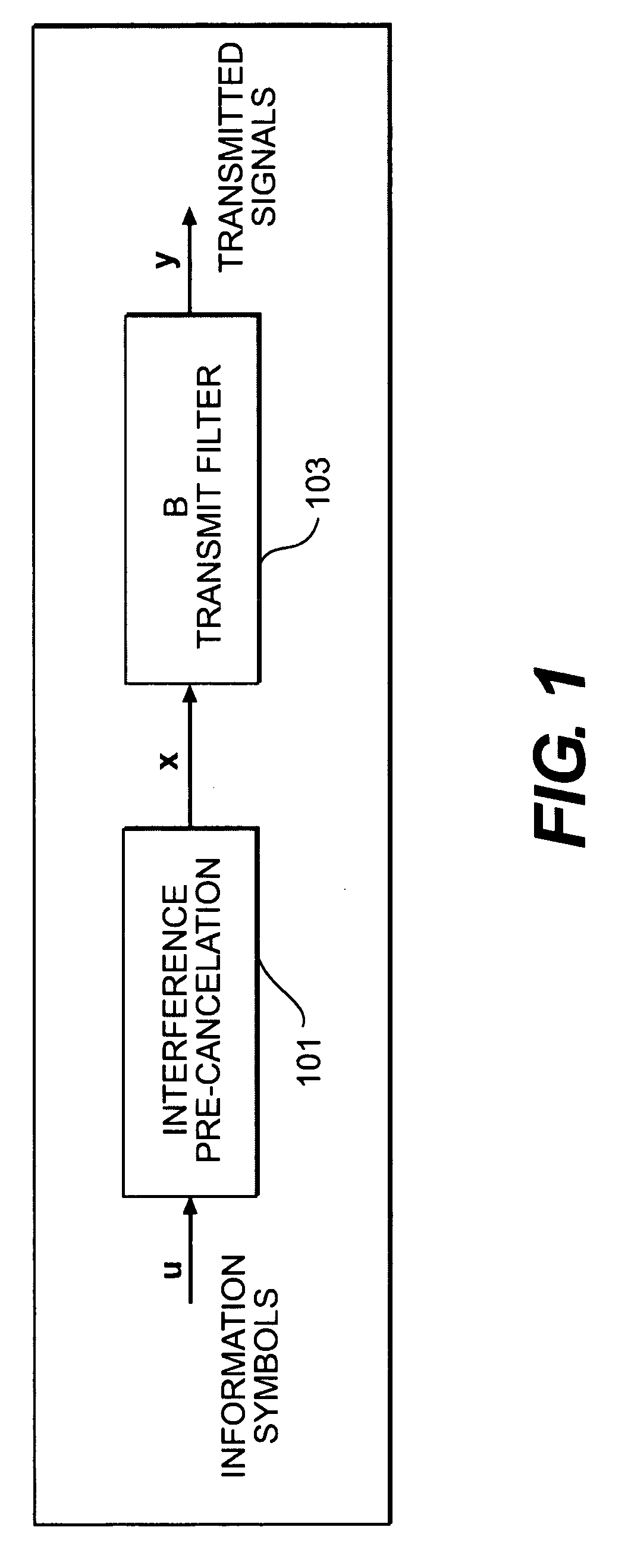
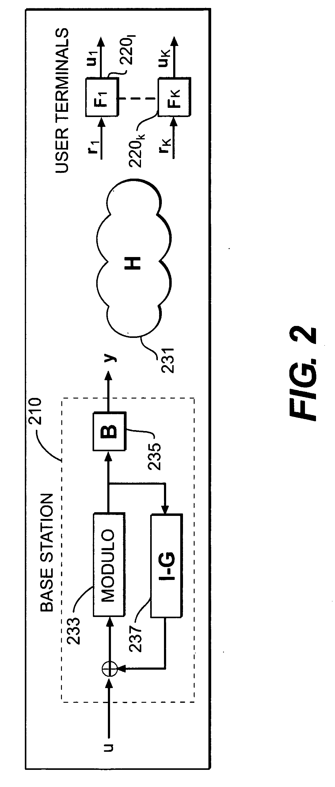
A technique is used to realize a generalized decision feedback equalizer (GDFE) Precoder for multi-user multiple-input multiple-output (MU-MIMO) systems, which significantly reduces the computational cost while resulting in no capacity loss. The technique is suitable for improving the performance of various MU-MIMO wireless systems including future 4G cellular networks. In one embodiment, a method for configuring a GDFE precoder in a base station of a MU-MIMO wireless system having k user terminals, each user terminal having associated therewith a feedforward filter. The method comprises computing a filter matrix C using one of a plurality of alternative formulas of the invention; and, based on the computation of the filter matrix C, computing a transmit filter matrix B for a transmit filter used to process a symbol vector obtained after a decision feedback equalizing stage of the GDFE precoder, a feedforward filter matrix F, and an interference pre-cancellation matrix G.

Description

FIELD OF THE INVENTION[0001]The present invention relates to multiple-input multiple-output (MIMO) communications systems. More specifically, the present invention relates to precoder configuration in MIMO systems.BACKGROUND OF THE INVENTION[0002]It is well known that a Generalized Decision Feedback Equalizer (GDFE) based precoder provides the optimal capacity solution for Multi-user Multiple-Input Multiple-Output (MU-MIMO) wireless systems. However, the computational cost of determining various filters associated with the GDFE Precoder is often prohibitive and is not suitable for many practical systems.[0003]There are several known Precoding techniques which can enable a Base Station (BS) equipped with multiple antennas to send simultaneous data streams to multiple user terminals (UTs) in order to optimize system capacity. In general, Precoding for a MU-MIMO system aims to optimize a certain criterion such as system capacity or bit error rate. Selected references are noted below, t...

Claims


Application Information

Patent Timeline
IPC IPC(8): H03H7/40H04L25/49H04B7/02
CPCH04L25/03343H04L25/03891H04B7/0619H04B7/0452H04L25/03057
Inventor GAUR, SUDHANSHU
Owner HITACHI LTD
Learn More