Combustion chamber for engine

A combustion chamber and engine technology, applied in combustion chambers, continuous combustion chambers, combustion methods, etc., can solve the problems of failing to meet low pollution requirements, high combustion zone temperature, low flame temperature, etc., to reduce temperature and reduce NOx emissions , the effect of reducing pollution

Active Publication Date: 2018-09-14
INST OF ENGINEERING THERMOPHYSICS - CHINESE ACAD OF SCI +1
View PDF8 Cites 0 Cited by
  • Summary
  • Abstract
  • Description
  • Claims
  • Application Information

AI Technical Summary

Problems solved by technology

Therefore, under large working conditions, the fuel is concentrated, the temperature of the combustion zone is high, and the low pollution requirements cannot be met, while the fuel-gas ratio is low, the flame temperature is low, the combustion zone is insufficient, and even the flame is turned off under small working conditions.

Method used


Image

  • Combustion chamber for engine
  • Combustion chamber for engine

Examples


Embodiment

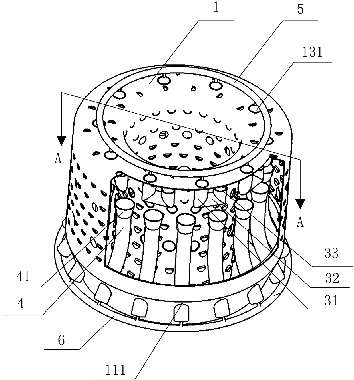
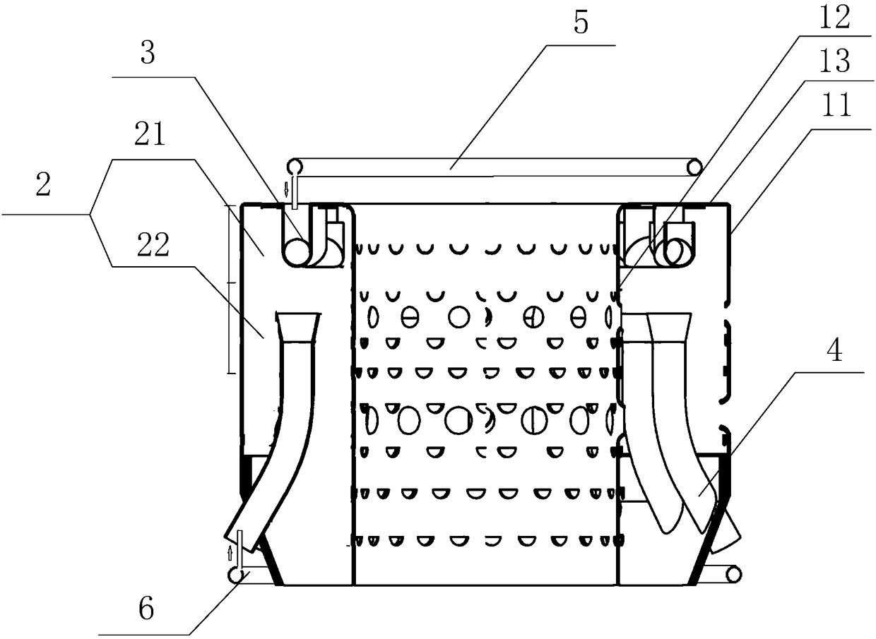
[0028] Example: such as figure 1 , figure 2 As shown, a combustion chamber for an engine includes a flame tube 1, a combustion chamber 2 is formed in the flame tube 1, and the front and rear parts of the flame tube 1 are respectively provided with a The first evaporation tube 3 and the second evaporation tube 4 for injecting fuel in the combustion chamber 2, one end opening of the first evaporation tube 3 is located in the combustion chamber 2, and the other end opening passes through the front end of the flame tube 1 and the fuel main pipe One end opening of the second evaporation tube 4 is located in the combustion chamber 2, and the other end opening passes through the rear of the flame tube 1 and communicates with the fuel main pipe. For different working conditions, only the first evaporation tube 3 is used to inject fuel into the combustion chamber 2 , or the first evaporation tube 3 and the second evaporation tube 4 are used to inject fuel into the combustion chamber ...


PUM


Abstract

The invention provides a combustion chamber for an engine. The combustion chamber for an engine is characterized in that a combustion cavity is formed in a flame tube, the front portion and the rear portion of the flame tube are provided with a first evaporation tube and a second evaporation tube respectively, wherein the first evaporation tube and the second evaporation tube are used for pre-mixing evaporation fuel and spraying the fuel to the combustion cavity; one end opening of the first evaporation tube is located in the combustion cavity, and the other end opening penetrates out of the front end of the flame tube and is in communication with a fuel main tube; and one end opening of the second evaporation tube is located in the combustion cavity, and the other end opening penetrates out of the rear part of the flame tube and is in communication with the fuel main tube. According to the combustion chamber for the engine, the first evaporation tube is arranged at the front end, thesecond evaporation tube is arranged at the rear portion, and a brand new combined evaporation tube combustion structure is provided; and the supply pressure of the structure fuel main tube is low, thespace classification of fuel combustion is realized, the temperature of the combustion area is effectively reduced, the purpose of reducing NOx emission is achieved, the flame stability of the head combustion chamber under a small working condition is improved, and the flameout boundary of the combustion cavity is expanded.

Description

technical field [0001] The invention belongs to the technical field of engines, in particular to a combustion chamber for an engine. Background technique [0002] Turbojet engine is a kind of turbine engine, which is characterized by completely relying on gas to generate thrust, and is usually used as the power of high-speed aircraft. There are two types of turbojet engines: centrifugal and axial. The turbojet engine works according to the "working cycle" mode. It sucks in air from the atmosphere, and the air gets energy and momentum after being compressed and heated, and then the air with energy and momentum is discharged from the propulsion nozzle. When spraying out of the engine, it drives the compressor and the turbine to continue to rotate at the same time, maintaining the working cycle. [0003] For example, the invention patent with the application announcement number of CN1743735A discloses an evaporating tube type micro-engine combustion chamber, which is composed...

Claims


Application Information

Patent Timeline
Patent Type & Authority Applications(China)
IPC IPC(8): F23R3/52
CPCF23R3/52Y02T10/12
Inventor 阮昌龙穆勇胡春艳刘存喜刘富强杨金虎徐纲朱俊强王月郭玉超于磊辉
Owner INST OF ENGINEERING THERMOPHYSICS - CHINESE ACAD OF SCI
Why Eureka
Try Eureka