
An environmentally friendly power component laying machine

A technology for power components and laying machines, applied in electrical components, circuits, photovoltaic power generation, etc., can solve the problems of high labor intensity, high labor cost, and low work efficiency, and achieve low labor intensity, low labor cost, and high work efficiency. Effect

Active Publication Date: 2020-04-03
金华美诺机电有限公司
View PDF9 Cites 0 Cited by
  • Summary
  • Abstract
  • Description
  • Claims
  • Application Information

AI Technical Summary

Problems solved by technology

[0003] In order to make up for the deficiencies of the existing technology, the present invention provides an environmentally friendly power module laying machine, which can solve the problems of high labor cost, high labor intensity, low work efficiency and uneven laying in the existing photovoltaic module laying process. Realize the function of automatic laying of photovoltaic modules, which has the advantages of low labor cost, low labor intensity, high work efficiency and neat laying

Method used


Image

  • An environmentally friendly power component laying machine
  • An environmentally friendly power component laying machine
  • An environmentally friendly power component laying machine

Examples


Embodiment Construction

[0017] In order to make the technical means, creative features, goals and effects achieved by the present invention easy to understand, the present invention will be further described below in conjunction with specific illustrations.

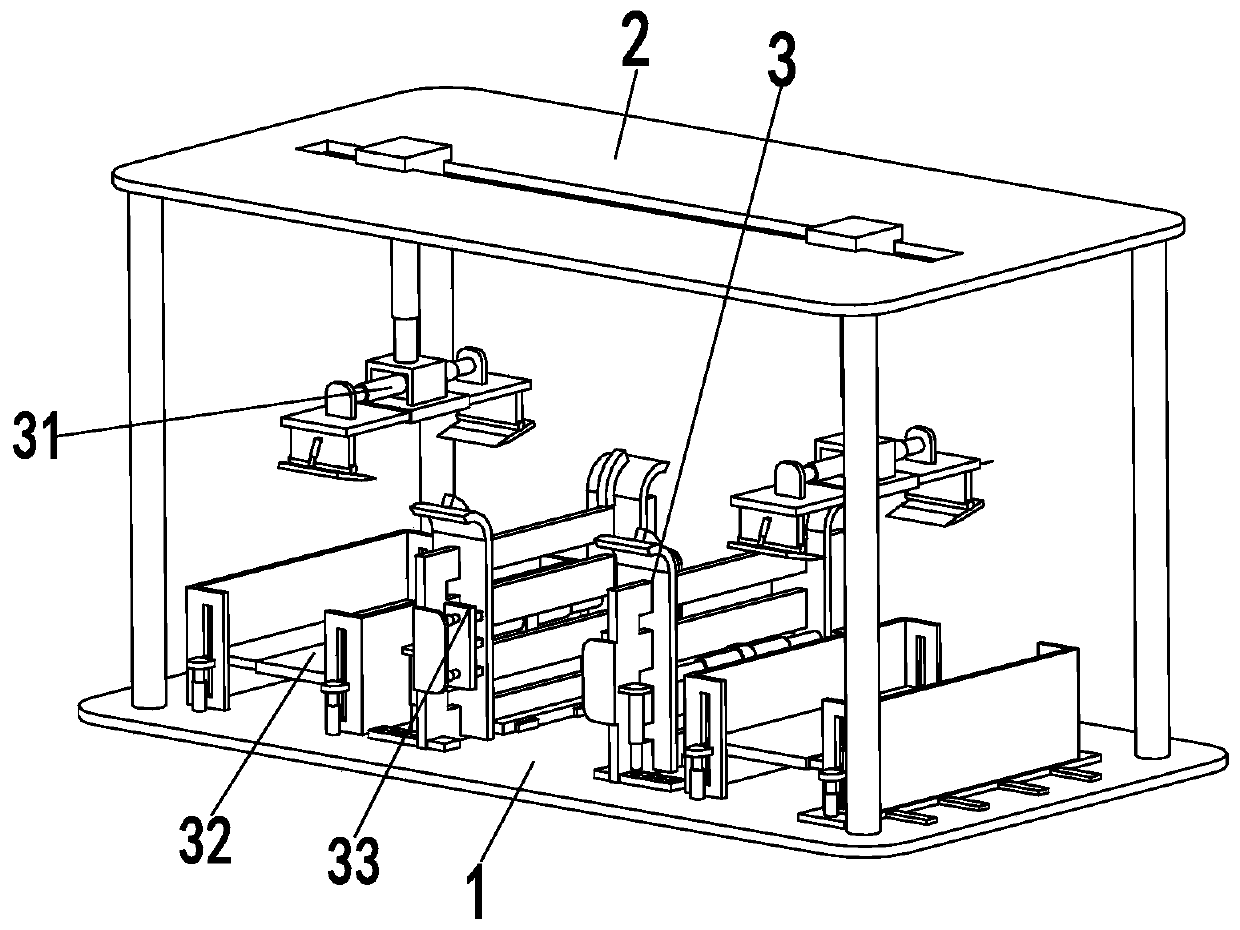
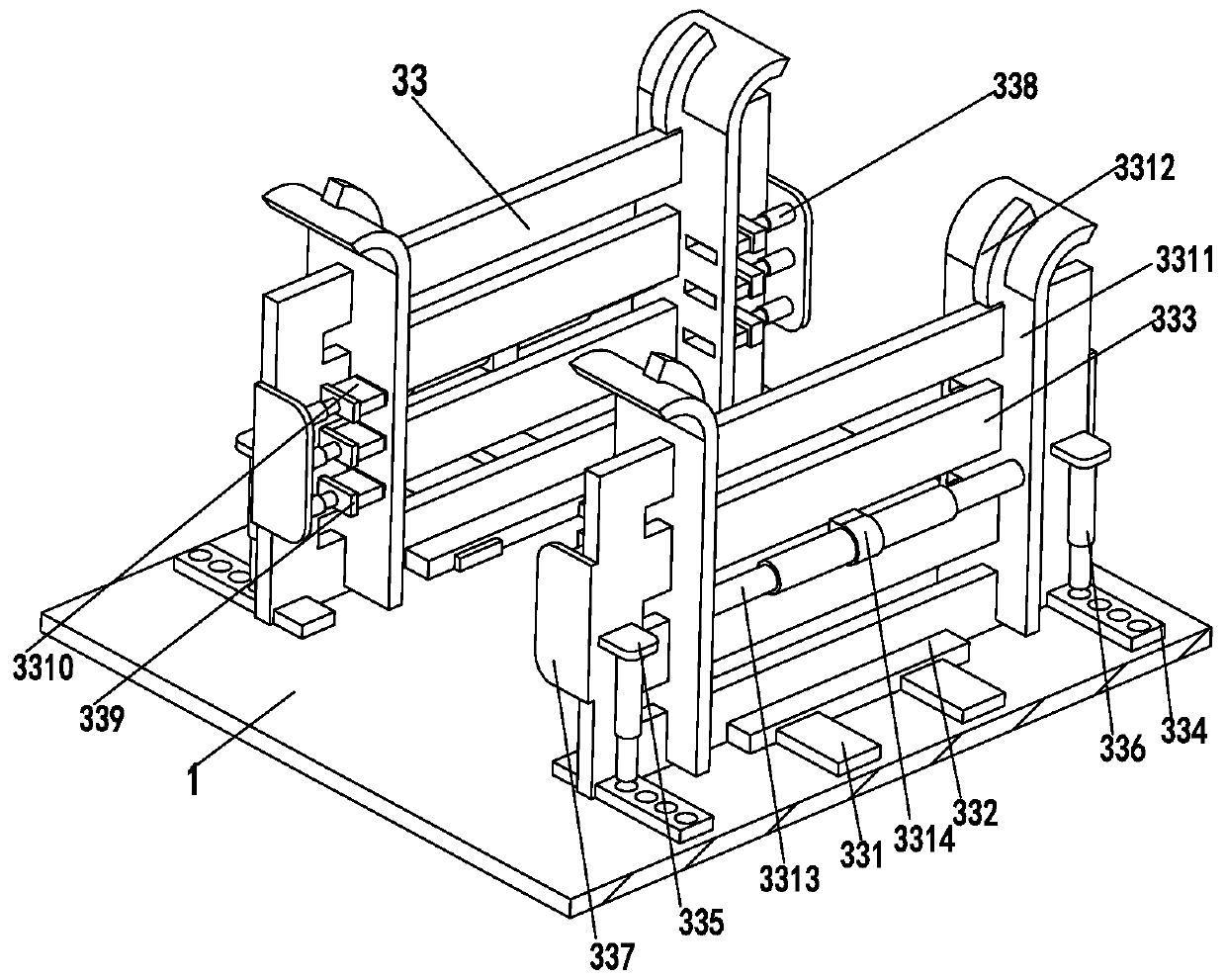
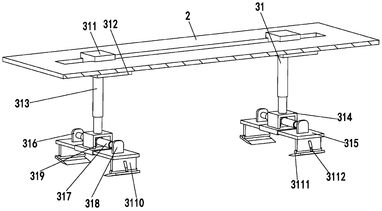
[0018] Such as Figure 1 to Figure 4 As shown, an environmentally friendly power component laying machine includes a base plate 1, a mounting frame 2, a grabbing mechanism 31, a material box 32 and a stacking mechanism 33. The mounting frame 2 is installed on the base plate 1, and the upper end of the mounting frame 2 is opened There is a sliding groove, and the grabbing mechanism 31 is installed in the sliding groove through a sliding fit. The number of grabbing mechanisms 31 is two, and the two grabbing mechanisms 31 are symmetrically arranged at the front and rear ends of the sliding groove. The bottom plate 1 is equipped with a material box 32 , the number of storage boxes 32 is two, and the two storage boxes 32 are symmetrically arranged at...


PUM


Abstract

The invention relates to an environmental protection electric power assembly laying machine. The environmental protection electric power assembly laying machine comprises a base plate, a mounting frame, two grabbing mechanisms, loading boxes and stacking mechanisms, wherein the mounting frame is arranged on the base plate; a sliding groove is formed in the upper end of the mounting frame; the grabbing mechanisms are arranged in the sliding groove in a sliding fitting mode; the two grabbing mechanisms are symmetrically arranged at the front and back ends of the sliding groove; the loading boxesare arranged on the base plate; the two loading boxes are symmetrically arranged at the front and back ends of the base plate; the stacking mechanisms are arranged at the middle of the base plate, and the two stacking mechanisms are arranged symmetrically; each component of a photovoltaic module are taken out from the loading boxes by the grabbing mechanisms, and then the grabbing mechanisms putthe components into the stacking mechanisms; and under the action of the stacking mechanisms, each component is stacked neatly without manual stacking, so that the laying effect is guaranteed. The environmental protection electric power assembly laying machine can realize the function of automatically laying the photovoltaic module, and has the advantages of low labor cost, low labor intensity, high work efficiency, neat laying and the like.

Description

technical field [0001] The invention relates to the technical field of environment-friendly electric power, in particular to an environment-friendly electric component laying machine. Background technique [0002] Solar cells are a new type of environmentally friendly power source, but single solar cells cannot be used directly as a power source. As a power source, several single cells must be connected in series or parallel and tightly packaged into modules. Solar photovoltaic modules (also called solar panels) are the core part of the solar power generation system and the most important part of the solar power generation system. Assembling single solar cells into photovoltaic modules requires laying the module strings, glass, EVA, glass fiber and backsheet in a certain order. At present, the most commonly used laying method is manual laying, which generally requires two workers to complete. One of them is responsible for fixing the parts, and the other person places the r...

Claims


Application Information

Patent Timeline
Patent Type & Authority Patents(China)
IPC IPC(8): H01L21/677H01L31/18
CPCH01L21/67706H01L31/1876Y02E10/50Y02P70/50
Inventor 范全通
Owner 金华美诺机电有限公司
Learn More