Disc type permanent magnet synchronous exhaust fan motor

A permanent magnet synchronous, electromechanical technology, applied to synchronous motors, electromechanical devices, magnetic circuits, etc. The effect of reducing copper loss

Pending Publication Date: 2018-09-14
包头天工电机有限公司
View PDF8 Cites 0 Cited by
  • Summary
  • Abstract
  • Description
  • Claims
  • Application Information

AI Technical Summary

Problems solved by technology

[0003] Since the permanent magnet rotor and stator are relatively long in the axial direction, this motor structure is suitable for use in places where the axial space of the motor is large, but it cannot be used in places where the space is relatively small

Method used


Image

  • Disc type permanent magnet synchronous exhaust fan motor
  • Disc type permanent magnet synchronous exhaust fan motor
  • Disc type permanent magnet synchronous exhaust fan motor

Examples


Embodiment Construction

[0028] The following description illustrates specific embodiments of the invention sufficiently to enable those skilled in the art to practice and reproduce it.

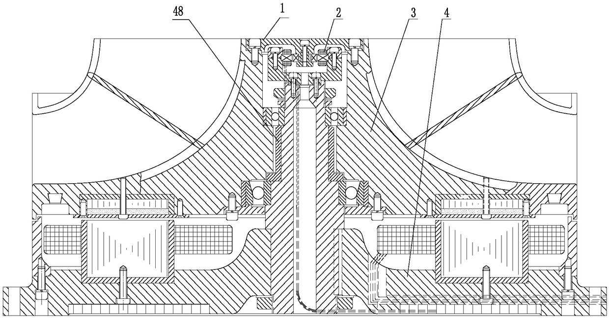
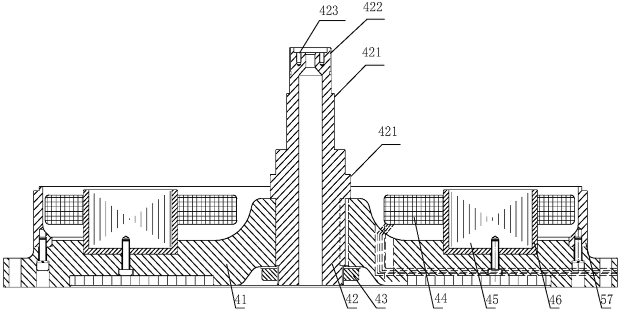
[0029] Such as figure 1 Shown is a schematic structural view of the disc-type permanent magnet synchronous exhaust fan motor of the present invention. Such as figure 2 Shown is a schematic structural view of the stator 4 in the present invention.

[0030] The structure of the disc type permanent magnet synchronous exhaust fan motor includes: a resolver cover plate 1, a rotary transformer 2, a fan permanent magnet rotor 3, and a stator 4. The stator 4 does not move, and after the stator coil 44 is energized, the fan permanent magnet rotor 3 rotates, and the fan 32 works to output wind energy.

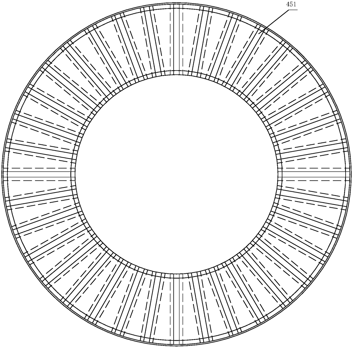
[0031] The stator 4 includes: a base 41, a rotating shaft 42, a first lock nut 43, a stator coil 44, a stator punch 45, a stator core pressure ring 46, and a seat ring 57; There is a coil fixing groove; the rotating shaft ...


PUM


Abstract

The invention discloses a disc type permanent magnet synchronous exhaust fan motor. The motor comprises a rotary transformer cover plate, a rotary transformer, a fan permanent magnet rotor and a stator. With the adoption of an axial magnetic circuit, the axial length of the motor is reduced, and the motor is suitable for being used in a place with small axial space and large radial space.

Description

technical field [0001] The invention relates to a synchronous motor, in particular to a disc-type permanent magnet synchronous exhaust fan motor. Background technique [0002] The existing motor magnetic circuits all adopt radial magnetic circuits, the stator windings of the motor are distributed on a circle according to certain rules, and the stator windings are fixed in the machine base. The permanent magnet rotor of the motor is a cylinder, and the permanent magnet rotor rotates in the stator to output mechanical energy and realize the conversion of electrical energy into mechanical energy. [0003] Since the permanent magnet rotor and stator are relatively long in the axial direction, this motor structure is suitable for use in places where the axial space of the motor is large, but it cannot be used in places where the space is relatively small. Contents of the invention [0004] The technical problem solved by the present invention is to provide a disc-type permanen...

Claims


Application Information

Patent Timeline
Patent Type & Authority Applications(China)
IPC IPC(8): H02K21/24H02K1/27
CPCH02K1/276H02K21/24
Inventor 宫国强乔振宁武春久滕裕国兰卫中刘永明
Owner 包头天工电机有限公司
Why Eureka
Try Eureka