Transportation system of unmanned restaurant
A transportation system, restaurant technology, applied in the direction of table utensils, tables, home utensils, etc., can solve problems such as time waste, and achieve the effect of increasing the running speed, narrowing the gap, and improving work efficiency
- Summary
- Abstract
- Description
- Claims
- Application Information
AI Technical Summary
Problems solved by technology
Method used
Image

Examples
Embodiment Construction
[0035] The present invention will be described in further detail below according to the drawings and embodiments.
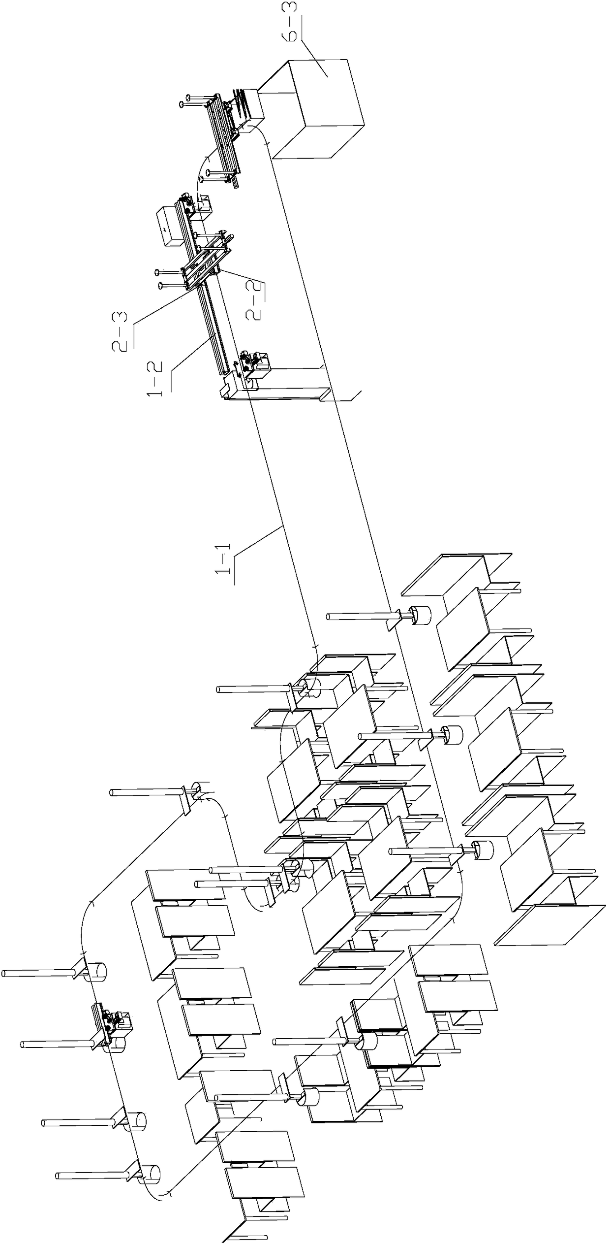
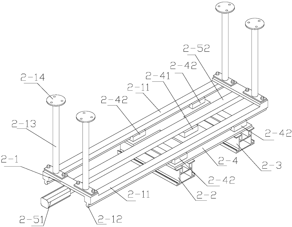
[0036] The transportation system for unmanned restaurants, including: track devices, track changing devices, multiple dining cars, and recovery devices.
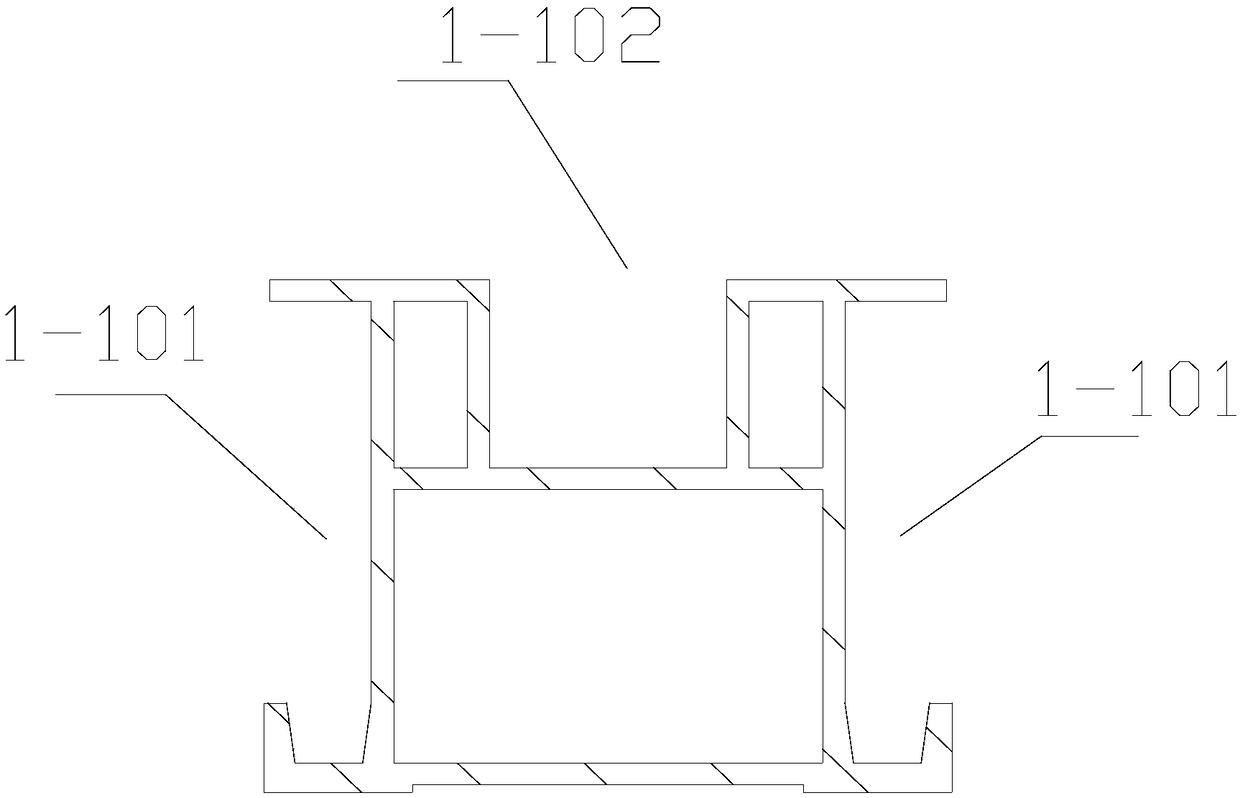
[0037] figure 1 It is an overall schematic diagram of the transportation system of the unmanned restaurant of the present invention, figure 2 It is a schematic diagram of the cross-sectional structure of the conveying track / outer track of the present invention, referring to figure 1 , figure 2 , a track device, comprising a delivery track 1-1 and an outer track 1-2, the left and right sides of the above-mentioned delivery track 1-1 and the above-mentioned outer track 1-2 are set as guide grooves 1-101 for transportation, and the top is routed The groove 1-102 is used for setting lines, etc. For the conveying track 1-1, it is a closed track with multiple bends, and the above-mentioned outer track 1-2 is a n...
PUM
 Abstract
Description
Claims
Application Information