
Scattering correction method and device for computer tomography image

A technology for scatter correction and tomographic images, applied in the field of image processing, can solve the problems of increased patient exposure, X-ray exposure, loss of primary signal, etc., to avoid scattering artifacts and reduce image quality.

Inactive Publication Date: 2018-09-18
GUANGZHOU HUARUI TECH
View PDF5 Cites 8 Cited by
  • Summary
  • Abstract
  • Description
  • Claims
  • Application Information

AI Technical Summary

Problems solved by technology

Hardware-based scattering methods mainly include anti-scatter grid, air gap and attenuation plate correction methods. However, anti-scatter grid and air gap methods often have the loss of the original signal, and often need to increase the patient's exposure dose to compensate for the attenuated The attenuation plate correction method requires a second scan of the patient, resulting in an increase in the patient's exposure dose; the hardware-based scattering correction method generally has the disadvantage of increasing the X-ray exposure dose, which is difficult to apply in clinical applications

Method used


Image

  • Scattering correction method and device for computer tomography image
  • Scattering correction method and device for computer tomography image
  • Scattering correction method and device for computer tomography image

Examples


Embodiment Construction

[0039] In order to make the purpose, technical solution and advantages of the present application clearer, the present application will be further described in detail below in conjunction with the accompanying drawings and embodiments. It should be understood that the specific embodiments described here are only used to explain the present application, and are not intended to limit the present application.

[0040] It should be noted that the term "first\second\third\fourth" involved in the embodiment of the present invention is only to distinguish similar objects, and does not represent a specific ordering of objects. Understandably, "first\ Second\third"where permitted, may interchange the specific order or sequence such that the embodiments of the invention described herein can be practiced in sequences other than those illustrated or described herein. For example, the terms "first side" and "second side" involved in the embodiments of the present invention are only used to...


PUM


Abstract

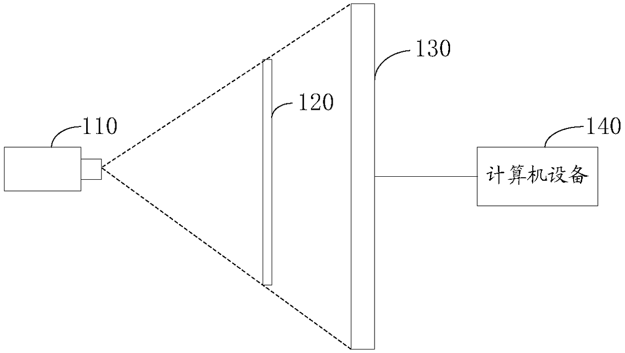
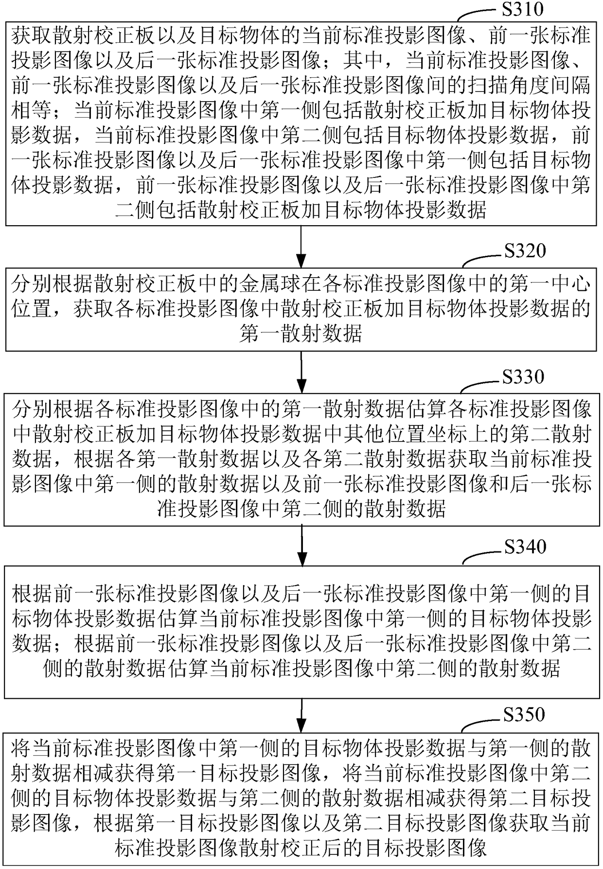
The invention relates to a scattering correction method for a computer tomography image, a system, computer equipment and a storage medium. According to the method, a current standard projection imageis subjected to scattering correction by using the image data of a previous standard projection image and a latter standard projection image, after a CBCT system uniformly acquires multiple standardprojection images through one circle of scanning, each standard projection image is subjected to the scattering correction by using the image data of the previous standard projection image and the latter standard projection image, it is effectively avoided that scattering artifacts in a reconstructed CT image are formed, a target object is only needed to be scanned once, the radiation dose of thetarget object is not increased, and the radiation dose of the target object is minimized while the quality of the CBCT image is ensured.

Description

technical field [0001] The present application relates to the technical field of image processing, in particular to a method, device, computer equipment and storage medium for scatter correction of computed tomography images. Background technique [0002] Cone-beam Computed Tomography (CBCT) plays a very important role in the field of medical imaging. However, since the detector used in CBCT is a flat-panel detector, the collimator cannot be used to block the scattered rays, so the reconstruction There are serious scattering artifacts in CBCT images. CBCT scattering seriously restricts the in-depth application and development of CBCT images in clinic. [0003] Traditional hardware-based scatter correction methods usually add several hardware tools to the X-ray imaging system to reduce the scattered rays reaching the flat panel detector to achieve the purpose of scatter correction, or to calculate the amount of scattered rays from the total ray The amount of scattered rays ...

Claims


Application Information

Patent Timeline
Patent Type & Authority Applications(China)
IPC IPC(8): A61B6/03
Inventor 齐宏亮陈宇思李翰威吴书裕骆毅斌
Owner GUANGZHOU HUARUI TECH
Learn More