[0027] The present invention will now be described in further detail with reference to the drawings. These drawings are all simplified schematic diagrams, which merely illustrate the basic structure of the present invention in a schematic manner, so they only show the structures related to the present invention.
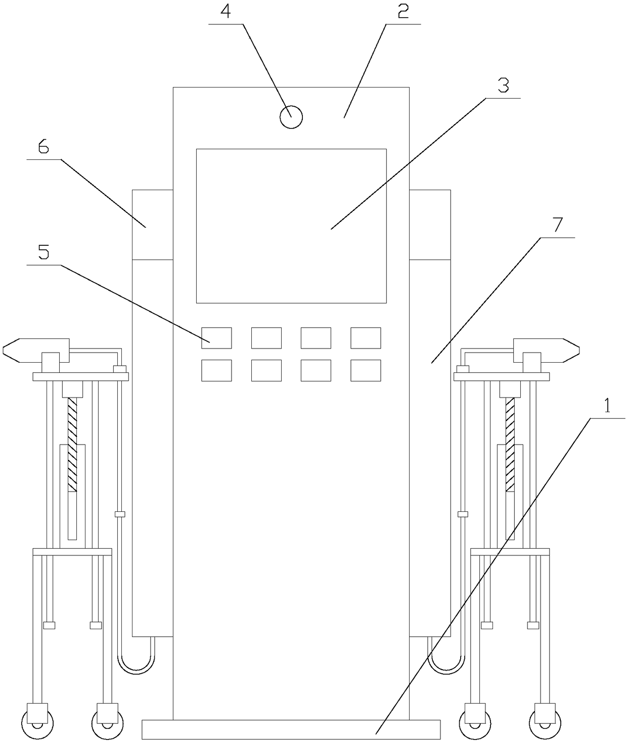
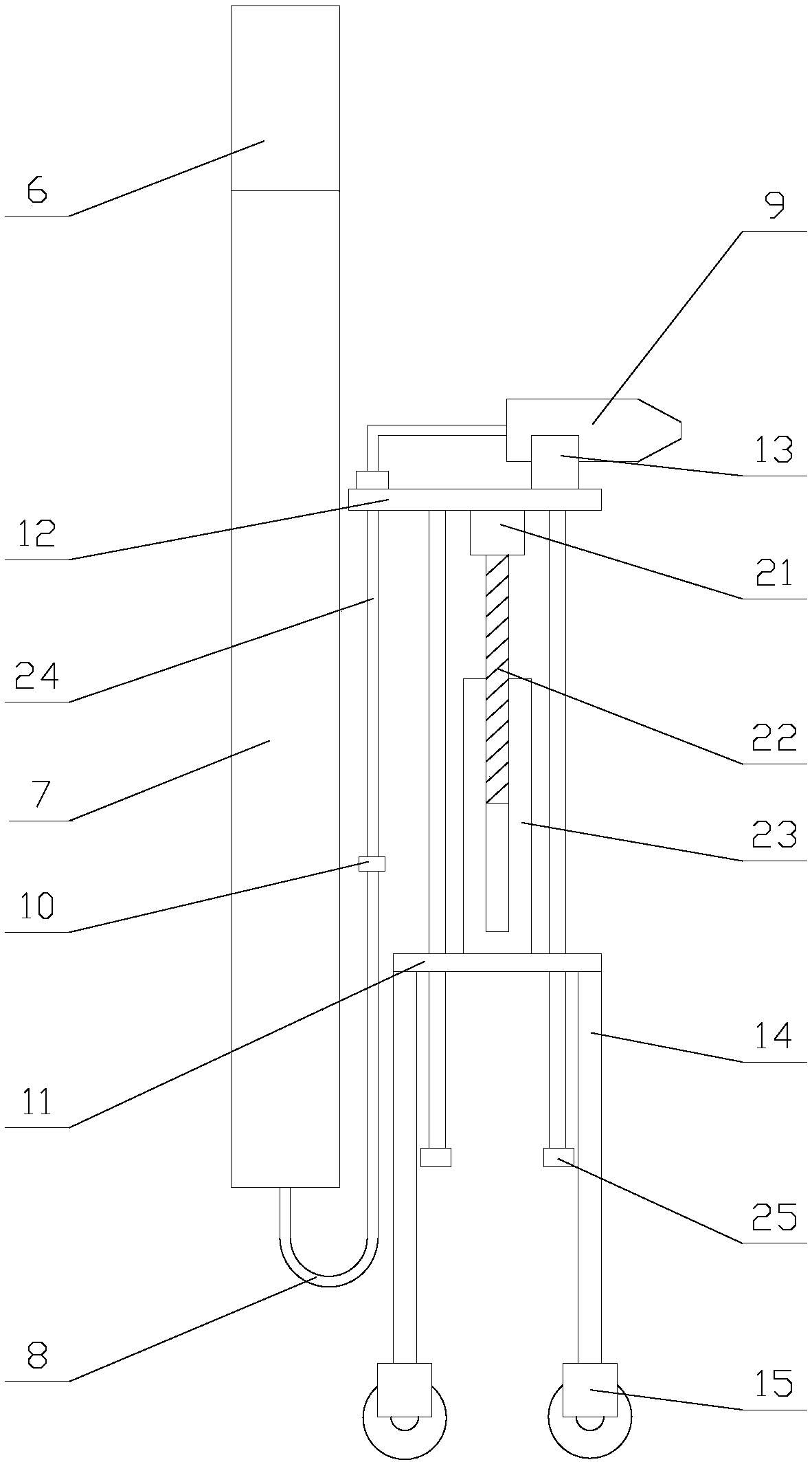
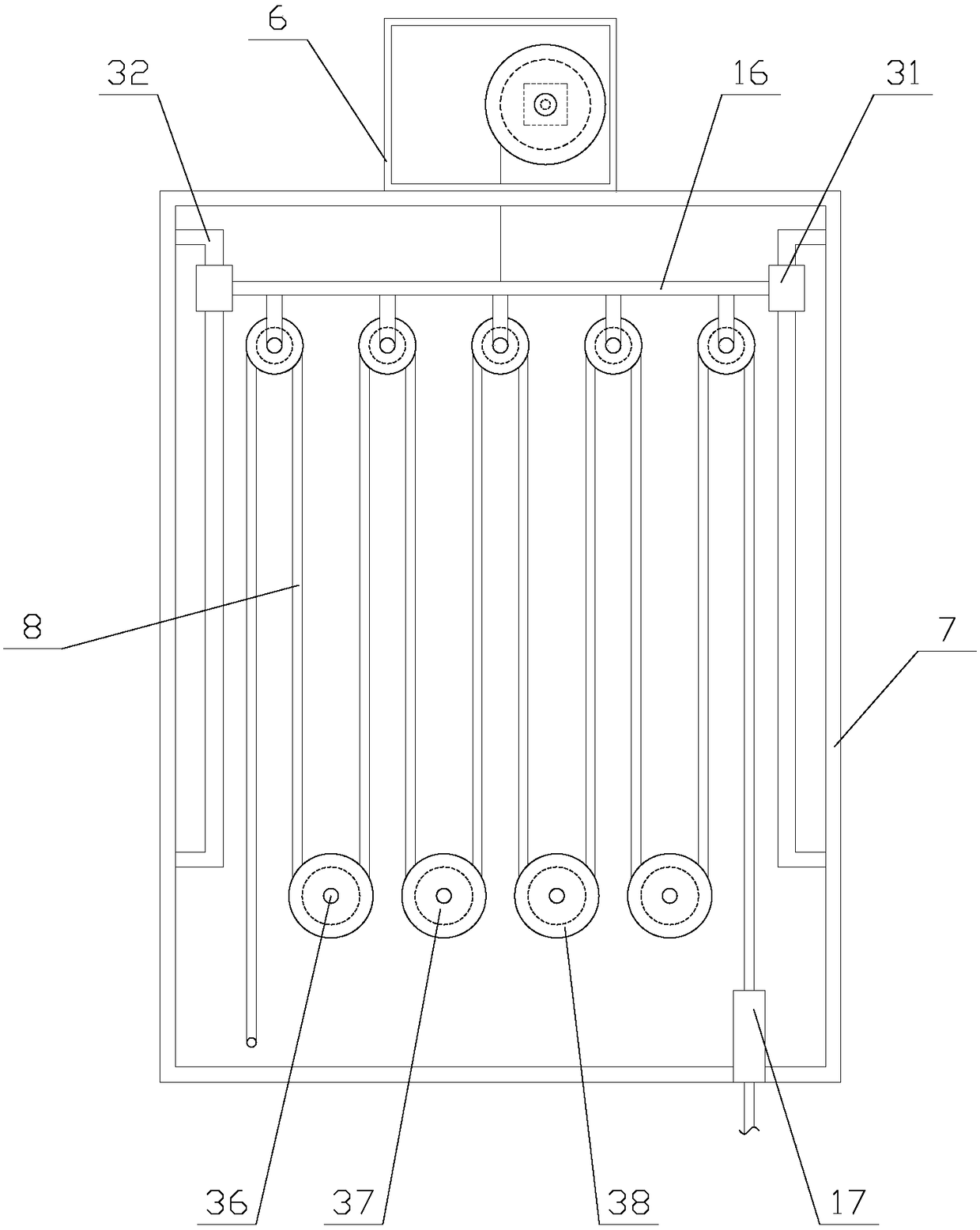
[0028] Such as figure 1 As shown, a safe, reliable and easy-to-use smart new energy vehicle charging pile includes a base 1, a main body 2, and two charging mechanisms. The main body 2 is fixed on the base 1, and the two charging mechanisms are respectively located on the main body 2. On both sides of, the main body 2 is provided with a display screen 3, a camera 4 and a number of control buttons 5, the main body 2 is provided with a PLC, and the display screen 3, the camera 4 and the control buttons 5 are all electrically connected to the PLC;
[0029] When the charging pile is in use, by operating the control button 5, the PLC controls the operation of the charging mechanism to charge the electric vehicle. The display screen 3 is used to indicate the charging time and other charging information, and the user's avatar in front of the main body 2 is collected through the camera 4 for easy operation Security Monitoring.
[0030] Such as figure 2 As shown, the charging mechanism includes a drive box 6, a storage box 7, a cable 8, a plug 9, a support mechanism, and two bumps 10. The drive box 6 and the storage box 7 are both fixed on the main body 2. The drive box 6 is located above the storage box 7, one end of the cable 8 is located in the storage box 7, and the other end of the cable 8 is connected to a plug 9 which is located above the supporting mechanism. 10 is fixed on the cable 8;
[0031] The supporting mechanism includes a bottom plate 11, a supporting plate 12, a supporting block 13, a lifting assembly, and four supporting legs 14. The supporting plate 12 is located above the bottom plate 11, and the lifting assembly is located between the push plate and the bottom plate 11. The supporting plate 12 is sleeved on the cable 8, the two bumps 10 are respectively located above and below the supporting plate 12, the supporting block 13 is fixed above the supporting plate 12, and the plug 9 is located above the supporting block 13. Four supporting feet 14 are respectively fixed at the four corners below the bottom plate 11, and universal wheels 15 are provided at the bottom ends of the supporting feet 14;
[0032] In the charging mechanism, one end of the cable 8 is received into the storage box 7, and the other end of the cable 8 is connected to the plug 9. By extending the plug 9 into the electric vehicle, the electric vehicle can be charged. When the device is idle, Use the support board 12 on the support mechanism and the support block 13 on the support board 12 to assist in supporting the plug 9 to prevent the plug 9 from falling on the ground and avoid short circuit caused by the accumulation of water in rain. In the support mechanism, you can pass through the bottom of the foot 14 The universal wheel 15 facilitates the movement of the bottom plate 11 and the pallet 12, and facilitates the movement of the bottom plate 11 and the pallet 12 to the vicinity of the electric vehicle. By extracting the plug 9 and extending the plug 9 into the car, the car can be charged. The end of the cable 8 away from the storage box 7 limits the moving distance of the cable 8 on the pallet 12 by two bumps 10, preventing the cable 8 from moving too long on the pallet 12, causing the plug 9 to fall on the ground On the upper side, the height of the pallet 12 can be conveniently adjusted by using the lifting assembly, which is convenient for charging the charging ports of cars of different heights.
[0033] Such as image 3 As shown, the drive box 6 is provided with a drive assembly, and the storage box 7 is provided with a storage mechanism. The storage mechanism includes a lifting plate 16, an outlet tube 17, a number of guide components and a number of rotating components. It is in transmission connection with the lifting plate 16, the outlet tube 17 is located at the bottom of the storage box 7, the outlet tube 17 is sleeved on the cable 8, the guide assembly is evenly distributed under the lifting plate 16, the rotating assembly Evenly distributed between the guide assembly and the bottom of the storage box 7, each rotating assembly is located between two adjacent guide assemblies;
[0034] When the equipment is idle, the drive assembly in the drive box 6 drives the lifting plate 16 to rise to increase the distance between the guide assembly and the rotating assembly. The cable 8 flows out from the outlet pipe 17 through the guide assembly and the rotating assembly in turn. When the distance between the components increases, most of the cables 8 are stored in the storage box 7. When the new energy vehicle needs to be charged, the PLC controls the drive components to run by operating the control button 5, and the lifting plate 16 is lowered , To reduce the distance between the guide assembly and the rotation, and it is convenient for the user to withdraw most of the cables 8 from the storage box 7.
[0035] Such as Figure 4 As shown, the guide assembly includes a horizontal shaft 18, a roller 19 and two suspension rods 20. Both ends of the horizontal shaft 18 are respectively fixed under the lifting plate 16 by two suspension rods 20, and the roller 19 is sleeved. On the horizontal axis 18, the cable 8 abuts above the roller 19.
[0036] In the guide assembly, the position of the horizontal shaft 18 is fixed by two suspension rods 20, and the roller 19 can rotate on the horizontal shaft 18, thereby facilitating the sliding of the cable 8 on the roller 19 and facilitating the storage of the cable 8.
[0037] Such as figure 2 As shown, the lifting assembly includes a first motor 21, a first drive shaft 22, a sleeve 23, and two orientation units. The first motor 21 is fixed under the pallet 12, and the first motor 21 is connected to the PLC. Electrically connected, the first motor 21 is drivingly connected to the top end of the first drive shaft 22, the bottom end of the first drive shaft 22 is set in the sleeve 23, the sleeve 23 is fixed under the bottom plate 11, two The two directional units are respectively located on both sides of the sleeve 23, and the connection between the sleeve 23 and the first drive shaft 22 is provided with threads matching the first drive shaft 22.
[0038] When the height position of the pallet 12 needs to be adjusted, the PLC controls the first motor 21 to start to drive the first drive shaft 22 to rotate, so that the first drive shaft 22 acts on the sleeve 23 through threads, so that the sleeve 23 and the first drive shaft The relative movement of 22 occurs. Since the sleeve 23 is fixed above the bottom plate 11, the first drive shaft 22 moves along its own axis, thereby realizing the height adjustment of the first motor 21 and the pallet 12.
[0039] Preferably, in order to ensure the stability of the lifting of the pallet 12, the orientation unit includes a directional rod 24 and a limiting block 25. The limiting block 25 is fixed under the pallet 12 by the directional rod 24, and the bottom plate 11 sets Set on the directional rod 24. The base plate 11 is sleeved on the orientation rod 24 to move the orientation rod 24 along its own axis to prevent the sleeve 23 from rotating when the first motor 21 drives the first drive shaft 22 to rotate, thereby ensuring the lifting of the pallet 12 The smoothness.
[0040] Such as Figure 5 As shown, the drive assembly includes a second motor 26, a second drive shaft 27, a bearing 28, a wire reel 29, and a cable 30. The second motor 26 and the bearing 28 are respectively fixed on the inner walls of both sides of the drive box 6. , The second motor 26 is electrically connected to the PLC, the second motor 26 is drivingly connected to one end of the second drive shaft 27, the other end of the second drive shaft 27 is arranged in the bearing 28, and the wire reel 29 It is sleeved on the second drive shaft 27, one end of the pull wire 30 is set on the wire reel 29, and the other end of the pull wire 30 is connected to the lifting plate 16.
[0041] When the lifting plate 16 needs to be controlled to move, the PLC controls the second motor 26 to start to rotate the second drive shaft 27 and drive the spool 29 to rotate, thereby tightening or loosening the cable 30. When the cable 30 is tightened, the cable 30 drives the lifting The board 16 rises to accommodate the cable 8. When the cable 30 is relaxed, the lifting board 16 descends, so that the user can draw out the cable 8 to charge the electric vehicle.
[0042] Preferably, the high strength and tensile strength of the carbon wire are utilized. In order to ensure the strength of the pull wire 30, the pull wire 30 is a carbon wire.
[0043] Preferably, in order to ensure the stability of the movement of the lifting plate 16, a slip ring 31 and a sliding rail 32 are provided on both sides of the lifting plate 16. The sliding ring 31 is fixed on the lifting plate 16, and the sliding rail 32 The shape is U-shaped, both ends of the slide rail 32 are fixed on the inner wall of the storage box 7, and the slide ring 31 is sleeved on the slide rail 32. The moving direction of the slip ring 31 is fixed by the slide rail 32 with a fixed position, so that the lifting plate 16 can be smoothly raised and lowered.
[0044] Preferably, in order to prevent the cable 8 from being detached from the roller 19, a clamping plate 33 is provided on both sides of the roller 19, and the clamping plate 33 is fixed on the horizontal shaft 18. The use of the two clamping plates 33 limits the range of the cable 8 sliding left and right on the roller 19, thereby preventing the cable 8 from falling off the roller 19.
[0045] Preferably, in order to prevent the roller 19 from sliding on the horizontal axis 18, an abutment block 34 is provided on the side of the boom 20 close to the splint 33, and one end of the abutment block 34 is fixed on the boom 20. The other end of the abutting block 34 abuts on the clamping plate 33. The sliding range of the clamping plate 33 is restricted by the abutting block 34, so as to prevent the roller 19 from sliding on the horizontal shaft 18.
[0046] Preferably, in order to facilitate the rotation of the roller 19, a side of the abutment block 34 close to the clamping plate 33 is provided with a notch, and a steel ball 35 is provided in the notch, and the steel ball 35 matches the notch. The center of the steel ball 35 is located in the recess, and the steel ball 35 abuts against the clamping plate 33. The steel ball 35 is used to convert the sliding friction between the abutting block 34 and the clamping plate 33 into rolling friction, which reduces the friction force experienced by the clamping plate 33 when rotating, thereby facilitating the rotation of the roller 19.
[0047] Preferably, in order to facilitate the storage of the cable 8, the rotating assembly includes a fixed shaft 36, a pulley 37, and two limiting plates 38. Both ends of the fixed shaft 36 are fixed on the inner walls of both sides of the storage box 7. The pulley 37 is sleeved on the fixed shaft 36, the two limiting plates 38 are respectively located on both sides of the pulley 37, the limiting plate 38 is fixed on the fixed shaft 36, and the cable 8 abuts against the pulley 37 Below. The position of the fixed shaft 36 is fixed, and the pulley 37 can rotate on the fixed shaft 36. The rolling range of the cable 8 on the fixed shaft 36 is restricted by the two limit plates 38, so as to facilitate the rotation of the cable 8 along the pulley 37. Move, thereby facilitating the storage of the cable 8.
[0048] In the charging pile, the plug 9 is assisted by the supporting block 13 in the supporting mechanism, and the sliding distance of the cable 8 on the supporting plate 12 is limited by the two bumps 10 to prevent the plug 9 from falling on the ground, leaving a safety hazard. And the universal wheel 15 at the bottom end of the feet 14 facilitates the movement of the support mechanism, so that the support mechanism can be moved to the vicinity of the electric vehicle for charging. Not only that, when the equipment is restricted, the lifting plate 16 is driven by the drive assembly to rise, and the rotating assembly and guide assembly are added. Therefore, most of the cables 8 can be stored in the storage box 7 to prevent the cables 8 from being dragged on the ground and worn on the ground. When charging is required, the driving assembly drives the lifting plate 16 to descend, reducing the rotating assembly and the guide assembly The distance between the two is convenient for the user to draw out the cable 8 for charging the car.
[0049] Compared with the prior art, the safe, reliable and easy-to-use smart new energy vehicle charging pile is provided with the plug 9 above the pallet 12 through the supporting mechanism, and the movement of the cable 8 on the pallet 12 is restricted by the bump 10 To avoid the plug 9 falling on the ground, leaving a safety hazard. Compared with the existing support mechanism, the support mechanism has a flexible structure. The universal wheel 15 can conveniently drive the bottom plate 11 and the pallet 12 to move to the vicinity of the car for charging. In this way, the lifting plate 16 is driven up and down by the drive assembly to realize the function of the storage mechanism to receive the cable 8. When charging, the lifting plate 16 is lowered to facilitate the extraction of the cable 8 to charge the car. Compared with the existing storage mechanism, The storage mechanism restricts the sliding range of the cable 8 through the clamping plate 33, prevents the cable 8 from falling off the roller 19, ensures the stability of the storage mechanism, and improves the practicability of the charging pile.
[0050] Taking the above-mentioned ideal embodiment according to the present invention as enlightenment, through the above-mentioned description content, relevant workers can make various changes and modifications without departing from the scope of the technical idea of the present invention. The technical scope of the present invention is not limited to the content of the description, and its technical scope must be determined according to the scope of the claims.