
Dam pile driver

A technology of pile driver and embankment, which is applied in the direction of sheet pile wall, building, foundation structure engineering, etc. It can solve the problems of destroying factory buildings, communication and transportation facilities, inconvenient flood fighting, and failure to achieve the effect, so as to achieve easy implementation and promotion, Easy to check and view, adjust the effect of position and angle

Inactive Publication Date: 2018-09-18
苏州倍儿壮养殖装备科技有限公司
View PDF4 Cites 3 Cited by
  • Summary
  • Abstract
  • Description
  • Claims
  • Application Information

AI Technical Summary

Problems solved by technology

Floods not only inundated houses and people, causing massive casualties, but also swept away people's property and flooded farmland, destroying crops and causing a drastic reduction in food production, leading to famine
Floods can also damage factories, communication and transportation facilities, thereby causing damage to the national economy
[0003] When a flood occurs, in order to prevent the disasters brought by the flood to people, people will take measures to build a dam to stop the flood, and the dam usually needs to drive piles at the mouth of the dam. However, when people drive piles, they usually set the fixed piles vertically When driving into the water, because the speed of the water flow and the situation at the bottom of the water are not known, the fixed piles driven into the dam mouth are often not at the predetermined position, and the desired effect cannot be achieved. Not only the fixed piles are wasted, but also a waste of time. When the pile is put into the water, the impact of the water flow on the fixed pile can shift the fixed pile from its original position. In serious cases, even the pile driver will also shift with the fixed pile, which brings a lot of inconvenience to the flood control

Method used


Image

  • Dam pile driver
  • Dam pile driver

Examples


specific Embodiment

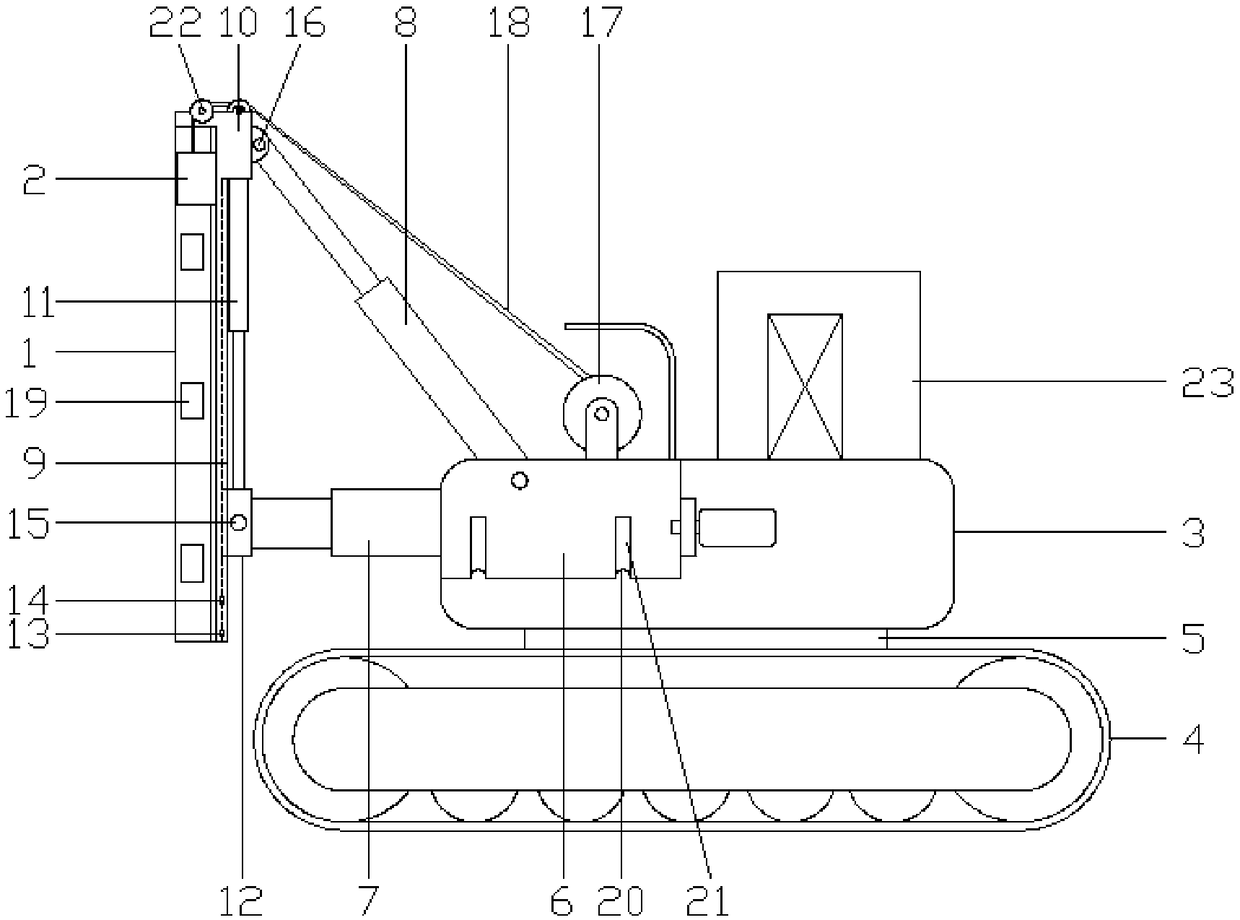
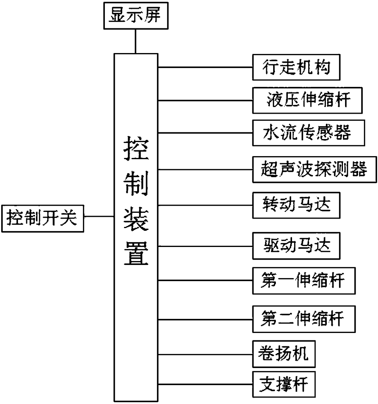
[0073]The user uses the present invention, a kind of embankment piling machine. When the user is using it, he turns on the control switch of the hydraulic telescopic rod, stretches the hydraulic telescopic rod on the pile frame to the water below the dam opening, and utilizes the water flow sensor and the ultrasonic wave on the hydraulic telescopic rod to The detector detects the water flow and terrain below the dam mouth, and displays the distribution speed of the water flow and the terrain below the dam on the display screen through the control device. The weight and volume of the fixed pile, calculate the displacement data of the impact of the water flow on the fixed pile and the data of the fixed pile entering the water at different positions and angles, so as to obtain the optimal water entry position and / or angle of the fixed pile; and can control the circuit board Control the first hydraulic telescopic rod and / or the supporting rod to adjust the position and / or angle of ...


PUM


Abstract

The invention discloses a dam pile driver. The dam pile driver comprises a pile frame, a pile hammer, an operating platform and a travelling mechanism. The travelling mechanism is connected with the operating platform through a turntable base. The operating platform is connected with the pile frame. The pile frame is connected with the pile hammer. The operating platform is provided with a turningtable. The turning table is connected with the pile frame through a first telescopic rod and a supporting rod. The pile frame is provided with a slide groove and a supporting table. A second telescopic rod is mounted on the supporting table and connected with a slide block. The slide block is connected with the slide groove and the first telescopic rod. A water flow sensor and an ultrasonic detector are mounted on the pile frame and connected with a control device. According to the pile driver, vertical pile driving is achieved, oblique pile driving in multiple directions at different anglesis achieved, a driven spud pile can follow the direction of waterflow, impact of the waterflow to the spud pile is attenuated, the pile driving efficiency and quality are improved, in addition, operation is easy and using is convenient, and implementation and popularization are convenient.

Description

technical field [0001] The invention relates to the field of machinery, in particular to an embankment pile driver. Background technique [0002] my country is one of the countries with frequent and serious flood disasters in the world. According to statistics, the economic losses and casualties caused by flood disasters in our country rank first among all kinds of natural disasters. Floods occur frequently, spread widely, come fiercely, and are extremely destructive. Floods not only inundated houses and people, causing a large number of casualties, but also swept away people's property and flooded farmland, destroying crops, resulting in a significant reduction in food production, resulting in famine. Floods can also damage factories, communication and transportation facilities, thereby causing damage to the national economy. [0003] When a flood occurs, in order to prevent the disasters brought by the flood to people, people will take measures to build a dam to stop th...

Claims


Application Information

Patent Timeline
IPC IPC(8): E02D7/08
CPCE02D7/08
Inventor 彭团生陈巧云
Owner 苏州倍儿壮养殖装备科技有限公司
Learn More