Slurry valve

A slurry and valve stem technology, applied in the field of slurry valve, can solve the problems of non-continuous grinding, low grinding efficiency, and no continuous force on the valve disc, and achieve the effect of reducing interference.

Inactive Publication Date: 2018-09-18
NEWAY VALVE SUZHOU
View PDF8 Cites 0 Cited by
  • Summary
  • Abstract
  • Description
  • Claims
  • Application Information

AI Technical Summary

Problems solved by technology

[0005] Therefore, the technical problem to be solved by the present invention is to overcome the problem that in the prior art, slurry valves and discharge valves that can be ground online cannot be continuously ground, and the valve disc does not have a continuous force acting on the valve seat, resulting in low grinding efficiency. Technical defects, thus providing a continuous online grinding, the disc can have a continuous force acting on the valve seat, improving the grinding efficiency of the slurry valve

Method used


Image

  • Slurry valve
  • Slurry valve
  • Slurry valve

Examples


Embodiment 1

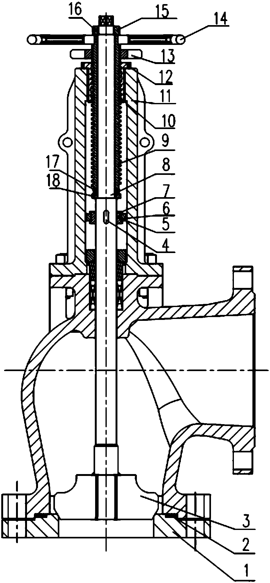
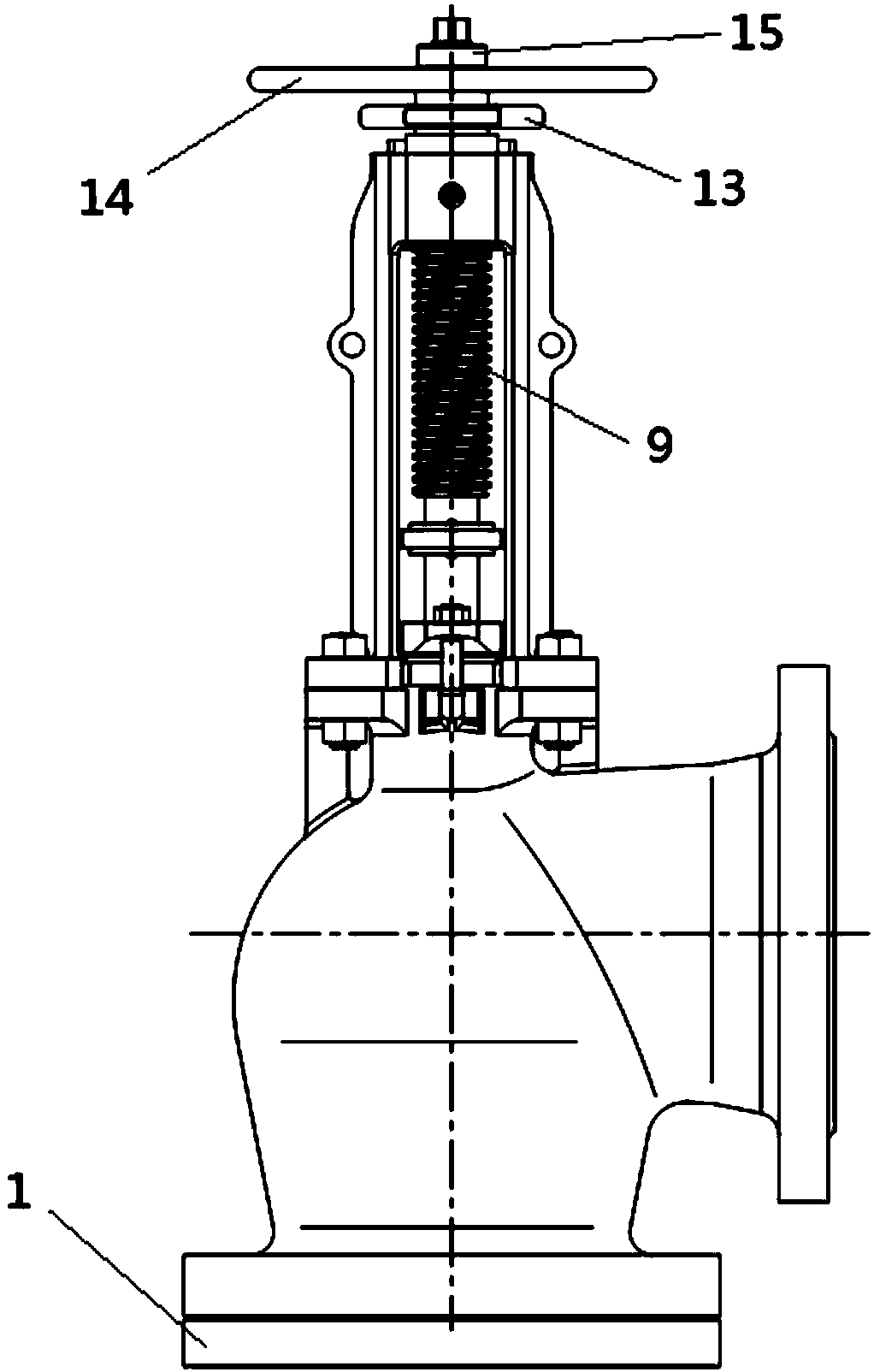
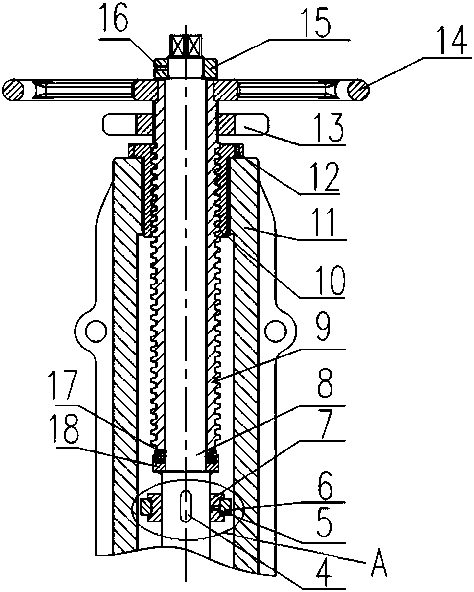
[0042] like Figure 1-7 As shown, it is a specific embodiment of a slurry valve involved in the present invention. The slurry valve includes: a valve seat 1, a valve body, a bracket 11, a valve stem 8, a valve disc 3, a valve stem nut 9, a first An anti-rotation structure, a second anti-rotation structure, two coupling structures and a second driving structure 14 .

[0043] In this embodiment, the valve seat 1 is fixed at the lower end of the valve body, the bracket 11 is fixed at the upper end of the valve body, a cavity is formed inside the valve body, and the side of the valve body A cavity inlet is formed, a cavity outlet is formed at the bottom of the valve body, the valve seat 1 is arranged at the cavity outlet, and the valve seat adopts a structure separated from the valve body, which is convenient for the valve seat repairs.

[0044] A winding pad 2 is provided at the joint between the valve seat 1 and the valve body, and the design of the winding pad 2 can improve t...

Embodiment 2

[0063] like Figure 8 As shown, different from Embodiment 1, the combined structure of the second anti-rotation structure and the second driving structure can also be replaced by a gear box 19, and at the same time, the structural form of the bracket is changed, and the bracket The upper end of the upper end is a flange surface, and the gear box 19 is connected with the flange surface of the bracket by a fourth screw 20. The gear box 19 includes a gear box nut 21 threaded with the valve stem nut 9 and Gearbox handwheel.

[0064] When the gear box hand wheel is turned, the gear box nut 21 rotates, causing the valve stem nut 9 to move up and down, thereby driving the valve stem to move up and down, so as to realize the opening and closing of the valve.

[0065] When grinding is required, turn the gear box handwheel, first adjust the valve to the closed state, then stop turning the gear box handwheel, so that the gear box nut 21 cannot rotate, and then connect the valve stem 8 ...


PUM


Abstract

The invention relates to the technical field of valves, in particular to a slurry valve. The slurry valve comprises a valve seat, a valve body, a bracket, a valve rod, a first rotation-preventing structure, a second rotation-preventing structure and two connecting structures; the valve seat is fixedly arranged at the lower end of the valve body, the bracket is fixedly arranged at the upper end ofthe valve body, the valve rod is arranged to penetrate through the bracket and the valve body in the axial direction, a valve clack matched with the valve seat is arranged at the bottom end of the valve rod, the upper portion of the valve rod is sleeved with a valve rod nut, and a gap is reserved between the valve rod nut and the valve rod; the first rotation-preventing structure is arranged on the valve rod and has a first state for limiting rotation of the valve rod and a second state for enabling the valve rod to rotate; the second rotation-preventing structure is arranged on the valve rodnut and has a third state for allowing the valve rod nut to rotate to drive the valve rod to move in the axial direction, and a fourth state for limiting rotation of the valve rod nut; and the two connecting structures are arranged at the two ends of the valve rod nut correspondingly and fixedly connected with the valve rod, and when the valve rod nut moves in the axial direction, the valve rod issynchronously driven to move in the axial direction through the connecting structures. According to the slurry valve, continuous on-line grinding can be achieved, and the grinding efficiency is improved.

Description

technical field [0001] The invention relates to the technical field of valves, in particular to a slurry valve. Background technique [0002] Alumina is a ceramic material with high hardness and high melting point. It has a wide range of applications in industry. The most typical one is industrial electrolytic alumina metal aluminum. In addition to electrolytic aluminum, alumina is also widely used in chemical industry. , such as as a petroleum cracking catalyst, etc., so the preparation of alumina is particularly important. In the process of preparing alumina, it will be applied to the alumina slurry valve. When the alumina slurry flows through the slurry valve or discharge valve, it is very easy to generate deposits and scabs inside the valve. If the surface position is not correct, it will seriously affect the sealing effect of the valve. If the scarring is serious, it will even block the valve and cause the valve to fail to open and close, which will seriously affect th...

Claims


Application Information

Patent Timeline
IPC IPC(8): F16K1/32F16K31/60F16K35/06F16K35/00
CPCF16K1/32F16K31/60F16K35/00F16K35/06
Inventor 王龙升周金荣王建华
Owner NEWAY VALVE SUZHOU
Why Eureka
Try Eureka