
Pipe jacking machine capable of improving safety performance

A technology of safety performance and pipe jacking machine, which is applied in the directions of mechanical equipment, pipeline laying and maintenance, pipes/pipe joints/pipe fittings, etc. It can solve the problems of low safety performance and achieve the effect of simple structure and improved safety factor.

Pending Publication Date: 2018-09-18
成都金玉雄辉建筑工程有限公司
View PDF6 Cites 2 Cited by
  • Summary
  • Abstract
  • Description
  • Claims
  • Application Information

AI Technical Summary

Problems solved by technology

[0003] The purpose of the present invention is to provide a pipe jacking machine with improved safety performance, which solves the problem that the existing pipe jacking machine cannot provide sufficient time for escape, resulting in low safety performance

Method used


Image

  • Pipe jacking machine capable of improving safety performance
  • Pipe jacking machine capable of improving safety performance
  • Pipe jacking machine capable of improving safety performance

Examples


Embodiment 1

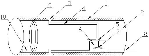
[0022] Embodiment 1: as figure 1 As shown, a pipe jacking machine for improving safety performance includes a shell 1 and a pipe jacking head 2, the shell 1 sets the pipe jacking head 2 inside; the pipe jacking head 2 is provided with a reducing The friction mud mixing chamber 6 and the escape air bag device; the thixotropic mud mixing chamber is placed at the bottom of the pipe jacking head 2 and 6 is connected to the shell 1 through the grouting pipe 4; the escape air bag device is detachably connected to the pipe jacking machine On the inner wall of the head 2; on the outer wall of the housing 1, several grouting ports 3 are evenly arranged; one end of the grouting pipe 4) is connected to the grouting port 3.

Embodiment 2

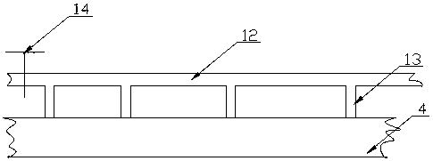
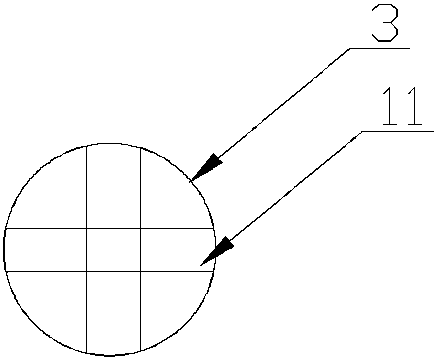
[0023] Embodiment 2: as figure 2 and 3 As shown, the section of the grouting port 3 is trumpet-shaped; the grouting port 3 is also provided with a diversion protrusion 11; the diversion protrusion 11 spans the grouting port 3 and covers part of the grouting port 3 ; The cross-section of the diversion protrusion 11 is cross-shaped.

Embodiment 3

[0024] Embodiment 3: as figure 1 As shown, the thixotropic mud mixing bin 6 is provided with a stirrer 7 and the thixotropic mud mixing bin 6 is connected with a water inlet pipe 8; the top of the thixotropic mud mixing bin 6 is provided with a slurry outlet and the The slurry outlet is connected to the grouting pipe 4; the slurry outlet is provided with a syringe pump 5.


PUM


Abstract

The invention discloses a pipe jacking machine capable of improving safety performance. The pipe jacking machine comprises a shell and a pipe jacking machine head. The pipe jacking machine head is sleeved with the shell, and the pipe jacking machine head is internally provided with a thixotropic slurry stirring bin and an escape airbag device; the thixotropic slurry stirring bin is placed at the bottom of the pipe jacking machine head and connected to the outer side wall of the shell through a slurry injection pipe, and the escape airbag device is detachably connected to the inner side wall ofthe pipe jacking machine head; and a plurality of slurry injection openings are evenly formed in the outer side wall of the shell, and one end of the slurry injection pipe is connected to the slurryinjection openings. A certain proportion of bentonite and water are mixed by the thixotropic slurry stirring bin and then injected onto the outer surface of the pipe jacking machine shell, so that thepipe jacking machine shell is wrapped with thixotropic slurry, and when a landslip accident occurs, a mud flow is effectively prevented from entering the pipe jacking machine. After being inflated, an escape airbag can block the mud flow in front of the machine head for making the more escape time for operators. The escape airbag device comprises a gas generating device, the rubber airbag and analerter; the gas generating device is provided with a gas outlet connected into the rubber airbag, and the alerter is connected to the gas generating device; and when the gas generating device startsto be inflated, the alerter gives an alarm to remind workers to evacuate rapidly.

Description

technical field [0001] The invention relates to the technical field of pipeline construction, in particular to a pipe jacking machine with improved safety performance. Background technique [0002] Pipe jacking construction is a construction technology for pipeline burial without excavation or less excavation. Pipe jacking construction is to use the jacking force generated by the jacking equipment in the working pit to overcome the friction between the pipeline and the surrounding soil, and push the pipeline into the soil according to the designed slope; Accidents such as landslides and groundwater gushing are prone to occur in the construction section; although the existing pipe jacking machines improve the safety of construction workers through preset escape channels, it is difficult to reserve more time for escape, resulting in low safety performance in pipe jacking construction . Contents of the invention [0003] The purpose of the present invention is to provide a ...

Claims


Application Information

Patent Timeline
Patent Type & Authority Applications(China)
IPC IPC(8): F16L1/028F16L1/06
CPCF16L1/028F16L1/06
Inventor 沈传雄
Owner 成都金玉雄辉建筑工程有限公司
Learn More