Phase adjusting method of laser scanning projector

A technology of laser scanning and adjustment method, applied in the directions of instruments, optics, optical components, etc., can solve the problem of MEMS mirror vibration back and forth phase dislocation and other problems, and achieve the effect of solving phase dislocation

Inactive Publication Date: 2018-09-18
GOERTEK OPTICAL TECH CO LTD
View PDF3 Cites 7 Cited by
  • Summary
  • Abstract
  • Description
  • Claims
  • Application Information

AI Technical Summary

Problems solved by technology

[0005] In view of the above problems, the object of the present invention is to provide a phase adjustment method of a laser scanning projector to solve the phase misalignment problem caused by the back and forth vibration of the MEMS mirror in the existing laser scanning projector

Method used


Image

  • Phase adjusting method of laser scanning projector
  • Phase adjusting method of laser scanning projector
  • Phase adjusting method of laser scanning projector

Examples


Embodiment Construction

[0030] In the following description, for illustrative purposes, many specific details are set forth in order to provide a comprehensive understanding of one or more embodiments. However, it is obvious that these embodiments can also be implemented without these specific details.

[0031] The specific embodiments of the present invention will be described in detail below with reference to the accompanying drawings.

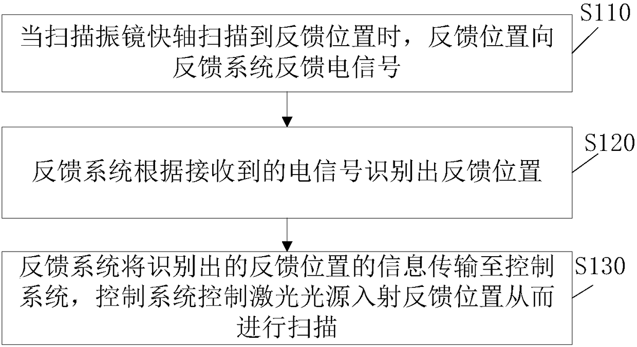
[0032] To illustrate the phase adjustment method of the laser scanning projector provided by the present invention, figure 1 The phase adjustment method of a laser scanning projector according to an embodiment of the present invention is shown.

[0033] Such as figure 1 As shown, the phase adjustment method of the laser scanning projector provided by the present invention includes:

[0034] The fast axis of the scanning galvanometer is used as a simple harmonic motion scanning image, and the feedback system set on the fast axis of the scanning galvanometer collects the inf...


PUM


Abstract

The invention provides a phase adjusting method of a laser scanning projector. The method comprises steps that a scanning galvanometer fast axis does the simple harmonic motion to scan an image, the information of the to-be-scanned image is collected by a feedback system set on the scanning galvanometer fast axis in real time, and a point in the motion range between 2Npi and (2N+1)pi of the scanning galvanometer fast axis is taken as the feedback position; when the feedback position is scanned by the scanning galvanometer fast axis, an electrical signal is fed back by the feedback position tothe feedback system; the feedback position is identified by the feedback system according to the received electrical signal; the identified information of the feedback position is transmitted by the feedback system to a control system, and the incident feedback position of a laser source is controlled by the control system for scanning. The method is advantaged in that a phase misalignment problemcaused by back and forth vibration of an MEMS mirror in a laser scanning projector in the prior art can be solved.

Description

Technical field [0001] The invention relates to the technical field of laser scanning projectors, and more specifically, to a phase adjustment method of a laser scanning projector. Background technique [0002] The core device in the laser scanning projector is the scanning galvanometer, which is divided into fast-axis scanning and slow-axis scanning. The fast axis direction uses the fast resonance of the MEMS mirror to achieve scanning. Now the laser light source is incident on the MEMS mirror. One cycle scan of the MEMS mirror will project two rows of images, but because it is a two-row image back and forth, it needs to be resolved. The time series problem of the laser light source between the two scanned lines. [0003] That is to say, when the collimated laser light source is incident on the MEMS mirror, the first laser point of the line when scanning from left to right, the first point in the next line should be the last one scanned from right to left Laser points, these two...

Claims


Application Information

Patent Timeline
Patent Type & Authority Applications(China)
IPC IPC(8): G03B21/20G02B26/10
CPCG02B26/10G03B21/2033G03B21/206
Inventor 杨乐宝
Owner GOERTEK OPTICAL TECH CO LTD
Why Eureka
Try Eureka