Control method for protecting inductive load current source

A control method and inductive load technology, applied in the direction of control/regulation system, regulation of electrical variables, instruments, etc., can solve problems such as small buffering, inductive reactance voltage damage to current source, and large input signal delay

A control method and inductive load technology, applied in the direction of control/regulation system, regulation of electrical variables, instruments, etc., can solve problems such as small buffering, inductive reactance voltage damage to current source, and large input signal delay

CN108549449AInactive Publication Date: 2018-09-18桂林海威船舶电器有限公司

Image

  • Control method for protecting inductive load current source
  • Control method for protecting inductive load current source
  • Control method for protecting inductive load current source

Examples


Embodiment Construction

[0026] The following will clearly and completely describe the technical solutions in the embodiments of the present invention with reference to the accompanying drawings in the embodiments of the present invention. Obviously, the described embodiments are only some, not all, embodiments of the present invention. Based on the embodiments of the present invention, all other embodiments obtained by persons of ordinary skill in the art without making creative efforts belong to the protection scope of the present invention.

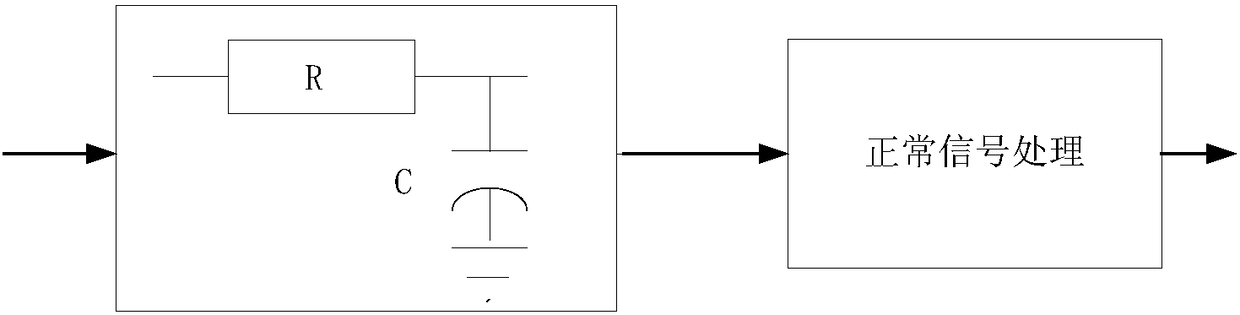
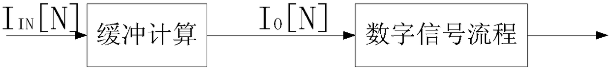
[0027] see figure 2 , a control method for protecting an inductive load current source, including an A / D converter, a buffer and a D / A converter connected in sequence, the signal is first transmitted from the A / D converter into the buffer for buffer calculation, and then passed through the buffer After the buffer calculation, the signal is sensed by the D / A converter, and then output through normal signal processing;

[0028] Let the maximum frequency point ...


PUM


Abstract

The invention relates to the technical field of current control, in particular to a control method for protecting an inductive load current source. The control method includes the steps that an A / D converter, a buffer and a D / A converter which are sequentially connected are included, signals is transmitted to the buffer from the A / D converter for buffer calculation firstly, after being subjected to buffer calculation through the buffer, the signals are sensed to the D / A converter, and then the signals are subjected to normal signal processing and then output. The requirements of buffer and dynamic indexes can be met at the same time, the change rate of the current source is controlled to be larger than the highest change rate of the dynamic indexes, and meanwhile the change rate enables the inductive reactance voltage to be not higher than the safety working voltage of the current source.

Description

technical field [0001] The invention relates to the technical field of current control, in particular to a control method for protecting an inductive load current source. Background technique [0002] A degaussing power supply is a controlled current source with an inductive load. In the process of use and debugging, inevitable step signals are often input. When the signal changes too much, due to the inductive characteristics of the load, a high inductive reactance voltage will be generated, resulting in damage to the current source. [0003] Existing technical solutions: increase the RC buffer current in the signal input loop, such as figure 1 shown; [0004] The disadvantages of this technical solution are: when the RC constant is too small, the buffer degree is small, the current change is still large, and the inductive reactance voltage may still damage the current source; when the RC constant is large, the input signal delay is large, which affects the performance of...

Claims


Application Information

Patent Timeline
18 Sep 2018
Publication
CN108549449A
IPC
G05F1/56
CPC
G05F1/561
Inventors
周世勋